Reanalysis of a Collapsed Anchored Bored Pile Wall
- Rana Jdidi
- Oct 16, 2023
- 5 min read
Updated: Nov 9, 2023
Learn how to Avert a Potential Failure!
In this case study we will evaluate a 16.1 m deep excavation supported by an anchored bored pile wall that collapsed during construction.
The model is simulated and reanalyzed with the DeepEX software program. The excavation was originally published in a paper by Devrim Alkaya and Burak YesilL (International Journal of the Physical Sciences Vol. 6(25), pp. 6009-6024, 23 October, 2011).
In the original publication, the authors presented their evaluation of the original model that collapsed during the construction.
The purpose of this exercise is to evaluate how different deep excavation analysis methods (Limit equilibrium, non-linear with elastoplastic soil springs, and finite elements method) compare to each other, and if or not they predict the original model collapse.
The bored concrete piles were 0.65m diameter in thickness and were supported by five levels of ground anchors.
Assumed soil properties are summarized in table 1:

ORIGINAL PROJECT ANALYSIS
The following image illustrates the original project analysis. According to the initial design, only 15.3 mm displacement was expected for the wall at the last stage.

Figure 1: Moment, Shear, Normal Load, and Bending Rigidity Distributions of Collapsed Retaining System.
PROJECT MODEL COLLAPSE
In the initial geotechnical investigation, the groundwater level was determined as 20 m, but during construction was encountered almost immediately after excavation.
The original authors describe that actual project displacements were increased due to the water pressures, and the installed tiebacks failed geotechnically, causing the bored pile wall to overturn and collapse.
The collapse in the actual model occurred during the excavation that followed the installation of the fourth anchor row, as presented in the images below:
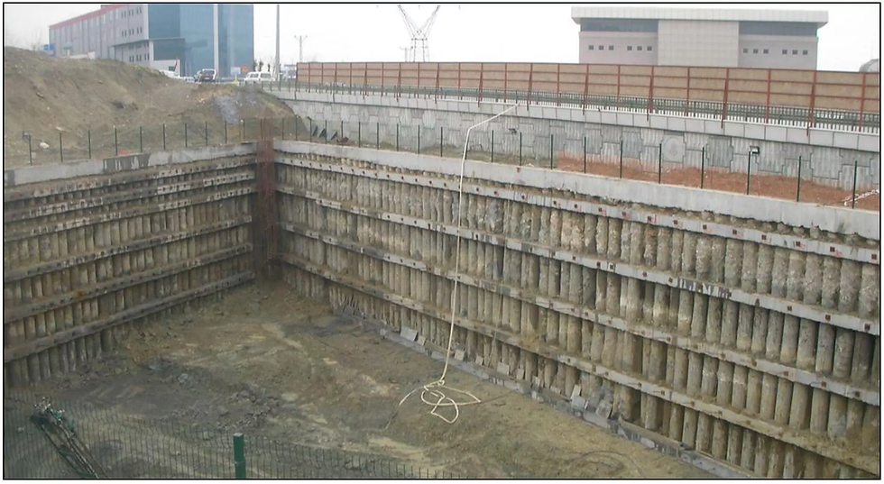

Figure 2: Model right before the collapse (up) and after the collapse, during the backfill procedure (down).

Design an Excavation in Minutes!
Request a FREE online live meeting, customized to your needs
Review fast all software features and capabilities
See the use of the software in different cases and scenarios
Our technical team can reply to all your questions
SIMULATION IN DEEPEX SOFTWARE
The model was simulated in DeepEX – Shoring Design software with all construction stages and analyzed with all implemented methods: Limit Equilibrium, Non-Linear and Finite Element Analysis.
The following image presents the generated model in the last construction stage.
Table 2 below presents the soil properties used within the software.

Figure 3: The model as created in DeepEX software – Last Construction Stage.
Table 2: Soil Properties and Stratigraphy in the DeepEX Model
Elev. (m) | Soil | Soil Type | ϒtot (KN/m3) | c’ or Su (kPa) | φ (deg) | | | |
-2.7 | F (Fill) | Sand | 19.1 | 0 | 30 | Exponential | 25000 | 0.5 |
-6 | C1 | Clay (Undrained) | 19 | 55 | 0 | Exponential | 20000 | 1 |
-13 | C3 | Clay (Drained) | 19.4 | 100 | 0 | Exponential | 28000 | 0.8 |
-15 | C2 | Clay (Undrained) | 19.2 | 13 | 10 | Exponential | 7000 | 0.9 |
-18 | C4 | Clay (Drained) | 18.3 | 32 | 13 | Exponential | 18000 | 1 |
-25 | C5 | Clay (Undrained) | 19.3 | 115 | 0 | Exponential | 45000 | 0.8 |
ANALYSIS ASSUMPTIONS IN DEEPEX
Limit Equilibrium Analysis (LEM)
Earth Pressures (Cantilever Excavation Stage): Active/Passive
Earth Pressures (Stages with supports): FHWA Apparent/Passive
Water Pressures: Simplified Flow
Wall Friction: No wall friction considered
Wall Analysis – Wall Beam: Free Earth Method (Cantilever) - California Trenching and Shoring Manual (CALTRANS)
Non-Linear Analysis (NL)
Wall Friction: 66% of the soil friction
Soil Springs Mesh Delta: 0.25m
Soil Models: Hyperbolic (Exponential)
Finite Element Analysis (FEM)
Wall Friction: 66% to 80% of the soil friction
Generated Mesh Density: Medium
Non-Linear Solver: Krylov-Newton
Soil Model: Soil Hardening Model
DEEPEX ANALYSIS RESULTS – MODEL COLLAPSE PREDICTION WITH ALL METHODS
With the Limit Equilibrium method, the software uses the conventional approach to calculate all pressures that are developed on the wall (earth active and passive side pressures, water pressures, external surcharges, seismic loads) and it calculates the net pressure diagrams for each stage.
The software uses the selected beam analysis method to calculate the wall moment and shear diagrams, the support reactions, and the wall embedment safety factors, as well as to estimate the wall displacements.
Wall embedment safety factors from stage seven and beyond the LEM method were calculated to be close to one or below, indicating insufficient wall embedment.
With the Non-Linear Analysis method, the software uses elastoplastic soil springs to simulate the connection of the soil with the wall.
Soil springs are also used to simulate the connection of the wall with installed supports.
The NL method takes into consideration the project staging.
The Winkler springs are initially placed in at-rest conditions, and along the construction stages, springs get activated and deactivated.
The software measures the effect on the springs and from that loading, it calculates all results.
With the Finite Element Analysis method, the software automatically generates a finite element mesh. DeepEX implements a series of soil models (Mohr-Coulomb, Exponential Soil Hardening and more) and a series of methods to calculate the results within the soil mass, considering full soil-structure interaction through the stages.
In the particular model, all 3 analysis methods in DeepEX showed the failure in the Construction Stage 9 (excavation stage right after the fourth anchor level was installed), by calculating the excessive moment diagram, the tiebacks geotechnical failure and the excessive displacements caused by the overturning of the wall system.
The following images illustrate the DeepEX calculated reactions and graphs in the project Stage 9 (failure stage).
Using the approximate method for the hardening soil model, which generates equivalent linear stiffnesses the FEM analysis would converge all the way to the last construction stage, but significant wall displacements and support forces would be observed.
With the exact HS model, the FEM analysis would not converge at Stage 7 when excavation for the 4th level was conducted, or at Stage 9 depending on the assumptions made.
This was an issue ready demonstrated by the wall embedment safety factors in both LEM and NL analyses.
From our review, it appears that the original paper incorrectly assumed the water table within the excavation at Stage 9.
The main conclusions from this exercise are that both the LEM and NL methods gave good indications of collapse conditions by producing large anchor forces, small wall embedment safety factors, and large base wall displacements. These findings were confirmed by a series of finite element simulations. If the engineers had used realistic soil properties, having all analysis methods within the same software package would have indicated the issues and the collapse could have potentially been averted.

Figure 4: LEM Analysis – Wall Moment and Displacement Diagrams, Support Reactions and Structural/Geotechnical Support Check Ratios, Wall Embedment Safety Factors (Stage 9 – Failure).

Figure 5: LEM Analysis – Net Pressures and Moment Diagrams in Stages 7 to 9.
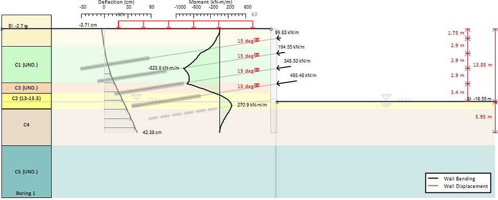
Figure 6: Non-Linear Analysis – Wall Moment and Displacement Diagrams, Support Reactions (Stage 9 – Failure).

Figure 7: Non-Linear Analysis – Support Check Ratios and Wall Embedment Safety Factors (Stage 9 – Failure).

Figure 8: FEM Analysis –Support Reactions, Soil Mass Displacement Shading (Stage 9 – Failure).

Figure 9: FEM Analysis – Wall Moment and Displacement Diagrams, Soil - Structure Deformation (Stage 9 – Failure).
DeepEX Can Design any Deep Excavation Model in Minutes!
Analyze Deep Excavations with All Methods: Limit Equilibrium - Non-Linear - Finite Element Analysis!
Design Anchored Walls, Braced Excavations, Cofferdams, Deadman Wall Systems, Top-Down + more!
AASHTO LRFD, CALTRANS, EUROCODES 2, 3, 7, 8, ACI, BS, Australian Codes, Chinese Codes +more!
Solutions for Geotechnical Engineering Professionals:
DeepEX: Deep Excavations Design Software

DeepFND: Pile Foundations Design Software

HelixPile Helical Piles Design Software