Cylinder VS Individual Plate Method – Advantages, limitations & Evaluation with DeepFND software
1. Introduction
Helical piles play a crucial role in foundation design, particularly in challenging soil conditions. Accurate estimation of end bearing capacity is essential for ensuring the structural stability of helical piles. This article delves into two prominent methods for end bearing capacity calculation – the Cylinder Method and the Individual Plate Method – and introduces DeepFND software as a comprehensive tool to analyze and optimize helical pile designs.

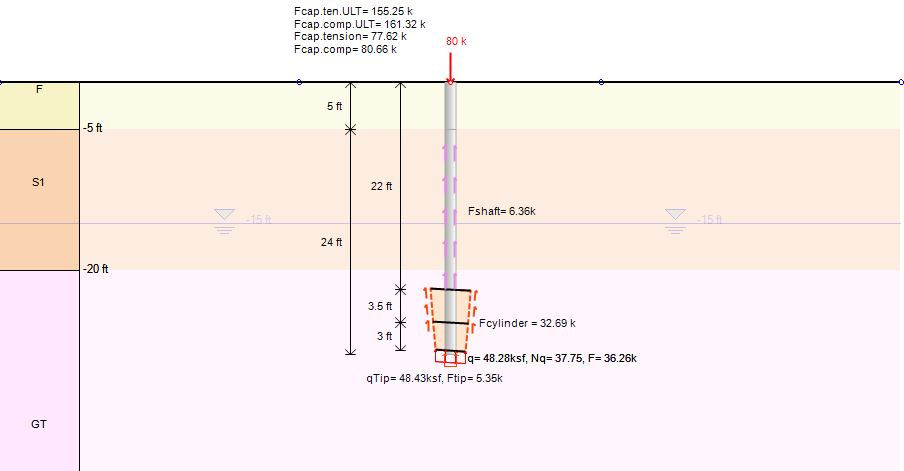
Figure: End bearing capacity for a helical pile in DeepFND – Cylinder (left) and individual plate method (right)
2. Methods for End Bearing Capacity Calculation
2.1 Cylinder Method:
In the cylinder method, the helical pile is assumed to act as a cylindrical shaft with a diameter equal to the diameter of the helix. The bearing capacity is calculated based on the shear strength of the soil along the cylindrical surface of the helix. The bearing capacity is often expressed using the Terzaghi's bearing capacity equation modified for helical piles.
The Cylinder Method simplifies the analysis by assuming helical piles as cylindrical shafts. This method offers simplicity and is suitable for preliminary design phases. However, its limitations include an oversimplified representation of soil-structure interaction, often leading to conservative estimations that might not capture the nuances of real-world conditions.
2.2 Individual Plate Method:
In contrast, in the Individual Plate Method, the helix is divided into individual bearing plates, and the bearing capacity is calculated for each plate. The total bearing capacity is then obtained by summing up the contributions from all individual plates and the end pile tip. This method considers the interaction between the soil and each individual helical plate.
The Individual Plate Method breaks down the helix into individual plates, considering the specific interaction between each plate and the soil. This method provides a more accurate assessment, especially in complex soil conditions. However, it demands detailed information about the helix geometry and increases computational complexity.
3. DeepFND Software
DeepFND emerges as a powerful solution for the axial and lateral analysis of various foundation pile types, encompassing helical and non-helical designs such as drilled, driven, caissons, micropiles, and CFA piles. One distinctive feature of DeepFND is its implementation of both the Cylinder and Individual Plate Methods for helical pile analysis. This integration allows engineers to directly calculate and compare results, facilitating a comprehensive evaluation of end bearing capacities.
4. Case Study: Helical Pile Analysis in DeepFND
To illustrate the capabilities of DeepFND, a case study was conducted involving a 4.5-inch diameter pipe with 3 helical plates in frictional soils. The software was employed to apply both the Cylinder and Individual Plate Methods for end bearing capacity calculation. The example data, which includes specific soil and helix parameters, showcases how DeepFND provides engineers with valuable insights into the performance of helical piles under varying conditions.
Tables 1 and 2 present the assumed soil properties and helical pile section. The following figures illustrate the model settings and the calculated tension and compression capacity results for each examined method in DeepFND software.
Table 1: Assumed soil properties and stratigraphy
Top El. (ft) | Soil (-) | γtot (pcf) | φ' (deg) | c' (psf) | Eload (ksf) | Exp (-) | Ksub(pci) |
0 | F | 120 | 30 | 0 | 300 | 0.5 | 30 |
-5 | S1 | 125 | 34 | 0 | 400 | 0.5 | 50 |
-20 | GT | 130 | 36 | 200 | 600 | 0.35 | 100 |
Table 2: Assumed helical pile structural section properties and length
Pile Length (ft) | Pile Diam. (in) | Pile Thick. (in) | Helix 1 Diam. (in) | Helix 1 Thick. (in) | Helix 2 Diam.(in) | Helix 2 Thick.(in) | Helix 3 Diam.(in) | Helix 3 Thick.(in) | Tip to 1st Plate (in) |
27 | 4.5 | 0.5 | 12 | 0.375 | 14 | 0.375 | 16 | 0.375 | 0.5 ft |

Figure: Soil properties and stratigraphy in DeepFND

Figure: Helical pile structural section properties in DeepFND

Figure: DeepFND – Comparison & checking summary table for both examined methods

Figure: Helical pile bearing capacities (tension and compression) in DeepFND – Cylinder method

Figure: Helical pile bearing capacities (tension and compression) in DeepFND – Individual plate method
5. Conclusion
In conclusion, accurate end bearing capacity calculation is vital for designing robust helical pile foundations. The Cylinder and Individual Plate Methods offer distinct advantages and limitations, emphasizing the need for a comprehensive approach. DeepFND, with its integration of both methods, streamlines the design process, allowing engineers to make informed decisions and optimize pile depths for the most critical conditions. As the field of foundation design evolves, leveraging advanced software tools like DeepFND becomes increasingly crucial for ensuring the structural integrity and efficiency of helical pile foundations.
Book A free web presentation:


