Die Auslegung von Tiefgründungen kann komplexer und herausfordernder sein, als es in einfachen Lehrbüchern erscheint. Die Bestimmung der geotechnischen Pfahltragfähigkeit ist eine Kunst mit vielen verschiedenen verfügbaren Methoden. Neben der Schätzung der Mantelreibung und der Endtragfähigkeit müssen wir oft auch die laterale Pfahltragfähigkeit bestimmen. Hinzu kommen Berechnungen der strukturellen Kapazität, Siedlungsleistung, Pfahlgruppen, Pfahlflöße und eine Vielzahl verschiedener Designcodes wie AASHTO LRFD und Eurocode 7 oder Australische Normen, und man könnte mehr Zeit mit der Erforschung der Entwurfsmethoden verbringen, unterschiedliche Berechnungslösungen verwenden, als eine funktionierende Lösung zu liefern. Deshalb haben wir DeepFND entwickelt, ein leistungsstarkes, benutzerfreundliches Programm für Tiefgründungen, entwickelt von Experten-Ingenieuren, um Ihnen beim Entwurf von Tiefgründungen zu helfen und Ihre Risiken zu minimieren. Das sind nicht nur Marketingworte. Wir sind Ingenieure mit Fachkenntnissen und leidenschaftlich daran interessiert, Ihnen zum Erfolg zu verhelfen.

Ein Paket löst alle wichtigen Herausforderungen im Entwurf von Tiefgründungen
✔ Axiale geotechnische Pfahllastberechnungen
✔ Schätzung der geotechnischen Eigenschaften (SPT oder CPT)
✔ Seitliche Pfahlanalyse
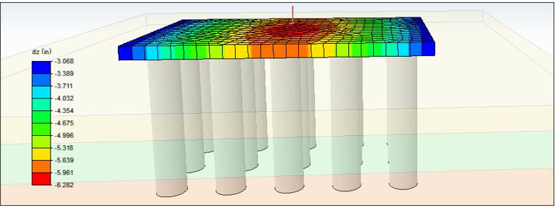
✔ Bodenfedern und 3D-Finite-Elemente-Analyse mit vollständiger Boden-Struktur
✔ Schätzung der Setzungsantwort
✔ Strukturelle Pfahltragfähigkeit, axial, Biegung, IBC, ACI, AISC, Australische Normen, Eurocode 2, 3
✔ Lastkombinationen wie AASHTO LRFD, Eurocode 7
✔ Praktisch alle Pfahltypen, gebohrte Pfähle, Bohrpfähle, eingetriebene Pfähle, Caissons, modellieren Sie jeden Pfahlquerschnitt, den Sie möchten!
✔ Pfahlgruppen and Pfahlflöße
✔ FHWA-Normen, GEC8, GEC10
✔ Mehr als das, Sie werden unseren herausragenden technischen Support haben, der Ihnen zum Erfolg verhilft.
1
Über
DeepFND - Software zur Auslegung von Tiefgründungen:
DeepFND deckt praktisch alle Aspekte des strukturellen und geotechnischen Fundamentpfahldesigns in einer überlegenen, interaktiven Umgebung ab.
All-in-one for deep foundation calculations
Engineers/non-analysts: Predict pile performance
Compute various pile types: drilled, driven, helical, etc.
Modify pile types, sections, and reinforcement easily
Thorough lateral and vertical pile analysis
Optimize embedment; design Single Piles/Pile Groups
2
Vorteile
Warum DeepFND wählen?

3
Unsere Tutorials
Wie die DeepFND-Software funktioniert
Deep FND SOFTWAREPAKET: BEGINNEN SIE MIT DER BASISVERSION - ERWEITERN SIE MIT ZUSATZMODULEN!
DeepFND bietet eine Reihe von Optionen und Zusatzmodulen, die die Softwarefähigkeiten erheblich erweitern und Ihre genauen Bedürfnisse abdecken können! Informieren Sie sich über die Preise und Lizenzierungen der DeepFND Softwarepakete.
-
ÜBERLEGENE INTERAKTIVE BENUTZEROBERFLÄCHESnailPlus ist eine äußerst benutzerfreundliche Software, die eine interaktive Modellbenutzeroberfläche bietet. In dem Modellbereich können wir alle Phasen erstellen und alle Projektparameter (externe Lasten, Bodennagelabschnitte, Spritzbetonabschnitte usw.) grafisch definieren. Alle Elemente im Modellbereich (Bohrung, Bodennägel, Verkleidung) können zugegriffen werden und ihre Eigenschaften können über benutzerfreundliche Dialogfelder definiert werden.
-
BERICHTE IN PDF UND MS WORD EXPORTIERENBERICHTE IN PDF UND MS WORD EXPORTIEREN Die Berichte von SnailPlus können Tabellen und Diagramme mit allen untersuchten Modelleigenschaften und berechneten Ergebnissen enthalten. Wir können auch wählen, alle Strukturberechnungsgleichungen und das Berechnungsverfahren in den Bericht aufzunehmen. Die Berichte von SnailPlus können vorab angezeigt, im PDF-Format exportiert oder im Word-Format exportiert werden, damit sie vom Benutzer weiter bearbeitet werden können. Designabschnitte für den Bericht auswählen Bauabschnitte für den Bericht auswählen Berichtsdiagramme anpassen Berichtslayout definieren Berichtsabschnitte definieren Möglichkeit, Gleichungen und Berechnungen der Bauabschnitte im Bericht aufzunehmen Berichtsvorschau Berichte im PDF- und Word-Format exportieren
-
BODENEIGENSCHAFTEN - SPT-AUFZEICHNUNGEN - CPT-PROTOKOLLEDie Bodentypen, Bodeneigenschaften und Stratigraphien können in SnailPlus durch benutzerfreundliche Dialogfelder einfach definiert werden. In SnailPlus können wir eine unbegrenzte Liste von Böden erstellen und schnell alle Bodeneigenschaften definieren. Die Software bietet mehrere Schätzwerkzeuge (SPT-Schätzer und teilweise Schätzwerkzeuge für jede Eigenschaft mit wissenschaftlichen Methoden und Gleichungen). In SnailPlus können wir direkt SPT-Aufzeichnungen und CPT-Protokolle hinzufügen, die vom Software zur Schätzung verschiedener Bodeneigenschaften verwendet werden können. Liste der Bodentypen definieren Liste der Stratigraphien definieren (Bohrungen) Werkzeuge zur Schätzung der Bodeneigenschaften SPT-Aufzeichnungen CPT-Protokolle
-
Modell Wizard - Erstellen Sie ein Modell in SekundenschnelleDer Modell Wizard von SnailPlus kann verwendet werden, um jede geneigte Oberfläche mit allen Bauphasen, Aushubarbeiten und der Installation von Bodennägeln und Verkleidungen in wenigen Minuten zu erstellen. Wir können die Registerkarten des Assistenten verwenden, um alle Projektparameter festzulegen (Parameter für die geneigte Oberfläche, Bodennägel - Kopfplatten und Schussbeton-Strukturabschnitte, Optionsstufen und Designstandards). Der Assistent erstellt das Modell automatisch und spart uns viel Zeit und Mühe bei der ersten Erstellung.
-
STRUKTURELLE UND GEOTECHNISCHE DESIGNKODESHelixPile hat viele internationale Designcodes und -standards für das Design und die Analyse (strukturell und geotechnisch) von Schraubpfählen implementiert. In HelixPile können wir ein Dienst- oder Faktordesign mit der Verwendung von US- und europäischen Standards durchführen. Wir können leicht zwischen mehreren US-, europäischen, australischen und chinesischen strukturellen Codes wählen. ACI 318-11 (Bewehrte Betonbauteile) ASD 1989 (Zulässige Spannungskonstruktion - Stahlbauteile) AASHTO LRFD 13. Ausgabe (Stahlbauteile) AISC 360 und 360-Zulässig (2010 und 2016) EUROCODE 2, 7 und 8 Spezifikationen AASHTO LRFD Lastkombinationen Europäische Codes (DIN, BS, XP94, DM, DA) Australische Standards (AS 3600, AS/NZS 4100) Chinesische Standards (CN)
-
PFAHLGRUPPEN - PFAHLFLÖSSEHelixPile kann sowohl Einzelschraubpfähle als auch Pfahlgruppen mit mehreren Pfählen entwerfen (das zusätzliche optionale Modul Pfahlgruppen ist erforderlich). Die Software kann auch Pfahlflöße entwerfen, wobei der kombinierte Effekt des Bodens unter dem Floß berücksichtigt wird (zusätzliches Modul zu unserer Pfahlgruppenoption). Einzelschraubpfähle Rechteckige Pfahlkappen Dreieckige Pfahlkappen Runde Pfahlkappen Sechseckige Pfahlkappen Achteckige Pfahlkappen Benutzerdefinierte Umfangspfahlkappen Pfahlflöße
-
PFAHLARTEN & HELIXKONFIGURATIONENHelixPile kann sowohl vertikale als auch laterale Designs von Schraubpfählen durchführen. Die Schraubpfähle in HelixPile können jede typische Form haben (Rohre, quadratische Voll- und Hohlprofile). In jedem Pfahl können wir eine unbegrenzte Anzahl von Helixkonfigurationen definieren und zuweisen. Die Pfähle können vergroutet werden. Schließlich können wir eine externe Ummantelung am Pfahlkopf verwenden, um die laterale Kapazität des Pfahls zu erhöhen. Stahlrohre Quadratische Vollstahlprofile Quadratische Hohlstahlprofile Unbegrenzte Helixkonfigurationen pro Pfahl Vergroutete Pfähle Verwendung einer externen Stahlummantelung
-
AXIALE & LATERALE PFAHLANALYSEHelixPile kann sowohl vertikale als auch laterale Pfahlanalysen durchführen. HelixPile verwendet sowohl die Einzelplatten- als auch die Zylindermethode und berichtet über die kritischsten Ergebnisse. Die allgemeinen und die Helicap-Gleichungen können ausgewählt werden. Für das vertikale Pfahldesign können wir entweder die Vesic- oder die Meyerhoff-Hansen-Methode verwenden. HelixPile berechnet und prüft das Installationsdrehmoment des Schraubpfahls. Für die laterale Pfahlanalyse kann HelixPile entweder die definierte Last am Pfahlkopf verwenden und die entwickelten Moment-, Scher- und Pfahlverschiebungsdiagramme berechnen, oder es kann eine Pushover-Analyse durchführen, bei der die erforderliche seitliche Last berechnet und präsentiert wird, um eine spezifizierte Pfahlkopfverschiebung zu erreichen. HelixPile kann auch eine Setzungsanalyse durchführen. In der Software können wir eines der implementierten Pfahlakzeptanzkriterien auswählen oder unser eigenes definieren.
-
ÜBERLEGENE INTERAKTIVE BENUTZEROBERFLÄCHEHelixPile ist eine äußerst benutzerfreundliche Software, die eine interaktive Modellschnittstelle bietet. Im Modellbereich können wir verschiedene Belastungsstadien erstellen und alle Projektparameter (externe Lasten auf dem Pfahlkopf, Pfahlabteilungseigenschaften usw.) grafisch definieren. Alle Elemente im Modellbereich (Bohrung, Pfahl, externe Lasten) können zugegriffen und deren Eigenschaften durch benutzerfreundliche Dialoge definiert werden.
-
EXPORTIERTE BERICHT IN PDF & WORDHelixPile kann umfangreiche Berichte für alle geprüften Designabschnitte (Pfähle) und Belastungsstadien erstellen. Die Berichte in HelixPile sind vollständig anpassbar - der Endbenutzer kann immer alle Berichtsabschnitte auswählen, die im endgültigen Bericht enthalten sein sollen. Die Berichte von HelixPile können Tabellen und Grafiken mit allen geprüften Modelleigenschaften und berechneten Ergebnissen enthalten. Wir können auch wählen, alle strukturellen Designgleichungen und Berechnungsverfahren in den Bericht aufzunehmen. Die HelixPile-Berichte können vorschauend betrachtet, als PDF oder im Word-Format exportiert werden, sodass sie vom Benutzer weiter bearbeitet werden können. Wählen Sie die zu berichtenden Designabschnitte aus Wählen Sie die zu berichtenden Bauphasen aus Passen Sie die Berichtsgrafiken an Definieren Sie das Layout des Berichts Definieren Sie die Berichtsabschnitte Möglichkeit, Gleichungen und Berechnungen der Phasen zu berichten Berichtsvorschau Berichte in PDF- und Word-Formaten exportieren
-
AUTO-MODELLGENERIERUNG UND -OPTIMIERUNGDer Modell-Assistent von HelixPile kann verwendet werden, um jedes Tiefgründungsmodell in Minuten zu erstellen. Wir können die Registerkarten des Assistenten verwenden, um alle Projektparameter (Analyseeinstellungen, Pfahltyp und strukturelle Abschnitt, externe Lasten und Designstandards) zu definieren. Der Assistent erstellt das Modell automatisch, was uns viel Zeit und Mühe für die anfängliche Erstellung erspart. HelixPile verfügt über ein automatisches Längenoptimierungswerkzeug. Die Software kann einen definierten Schritt verwenden, um die Pfahltiefe bis zu einer definierten Tiefengrenze zu erhöhen, wobei die axiale Zug- und Druckkapazität in jedem Schritt berechnet wird.
-
BODENEIGENSCHAFTEN - SPT-AUFZEICHNUNGEN - CPT-PROTOKOLLEDie Bodentypen, Bodeneigenschaften und Stratigraphien können in HelixPile einfach über benutzerfreundliche Dialoge definiert werden. In HelixPile können wir eine unbegrenzte Liste von Böden erstellen und schnell alle Bodeneigenschaften definieren. Die Software bietet mehrere Schätzungswerkzeuge (SPT-Schätzer und teilweise Schätzungswerkzeuge für jede Eigenschaft mit wissenschaftlichen Methoden und Gleichungen). In HelixPile können wir direkt SPT-Aufzeichnungen und CPT-Protokolle hinzufügen, die von der Software verwendet werden können, um verschiedene Bodeneigenschaften zu schätzen. Liste der Bodentypen definieren Liste der Stratigraphien (Bohrungen) definieren Schätzungswerkzeuge für Bodeneigenschaften SPT-Aufzeichnungen CPT-Protokolle
-
MEHRERE WANDTYPENDie QuayWalls-Software kann jede Art von Schwerkraftquerschnittswand entwerfen, indem sie Boden-, Wasser-, Wellen- und seismische Drücke auf das Wandsystem berechnet. QuayWalls kann für Entwurf und Analyse von: Kragwände Segmentwände Boxkaissonwände mit Bodenfüllzonen T-förmige Wände Benutzerdefinierte Wände
-
WELLENDRUCK & ÜBERSTRÖMUNGQuayWalls kann Wellendruck mit einer Reihe von etablierten Methoden berechnen. Die anfänglichen Wellenhöhen und Wellenlängen können mit implementierten Empfehlungen geschätzt oder manuell durch den Benutzer über ein benutzerfreundliches Dialogfeld definiert werden. Schließlich kann QuayWalls automatisch Überströmungsraten schätzen, da es Berechnungen des durchschnittlichen Überströmungsvolumens unter Verwendung der PROVERBS-Gleichungen durchführen kann. Goda SainFlou Küsteningenieurhandbuch 2011 Allsop PROVERBS
-
STABILITÄTSANALYSE VON BÖSCHUNGEN & NAGELWANDKONSTRUKTIONSnailPlus ermöglicht die globale Stabilitätsanalyse von Böschungsoberflächen (einfach oder mit Bodennägeln verstärkt). SnailPlus kann die kritischste Böschungsoberfläche berechnen und den Sicherheitsfaktor für die Böschungsstabilität unter Verwendung mehrerer wissenschaftlicher Methoden ermitteln. Bodennägel können in Böschungsoberflächen verwendet werden. SnailPlus berechnet die Auswirkungen der Bodennägel auf die Stabilitätsanalyse der Böschung. Bishop-Methode Morgenstern-Price-Methode (Allgemeines Grenzgleichgewicht) Spencer-Methode Französische Clouterre-Normen für die Bodennagelkonstruktion
-
VOLLSTÄNDIGES DESIGN DER SHOTCRETE-VERKLEIDUNGSnailPlus kann die Shotcrete-Verkleidung entwerfen. Verkleidungen in zwei Stufen (temporär und permanent) können ebenfalls definiert und mit der Software analysiert werden. SnailPlus führt Überprüfungen an den Kopfplatten der Bodennägel durch. Design der Shotcrete-Verkleidung Zweistufige Verkleidung verfügbar Überprüfungen der Kopfplatten
-
DESIGNNORMEN UND SPEZIFIKATIONENSnailPlus hat verschiedene Standards und Spezifikationen für das Design von Bodennägeln und Shotcrete-Verkleidungen implementiert. In SnailPlus können wir ACI- und FHWA-Spezifikationen für das strukturelle Design auswählen. In der Software können wir Methoden des Grenzzustandes der Gebrauchstauglichkeit oder des Grenzzustandes der Tragfähigkeit verwenden. ACI Direktmethode FHWA- und FHWA-LRFD-Methoden LRFD WSDOT 2019 (GDM) ASD-Sicherheitsfaktoren LRFD FHWA GEC-7 EUROCODE 7 - ULS-Ansatz
-
SUCHOPTIONEN FÜR MEHRERE BÖSCHUNGSOBERFLÄCHENSnailPlus kann die kritischste Böschungsoberfläche unter Verwendung verschiedener Suchmethoden für Böschungsoberflächen lokalisieren und berichten: Kreisförmige Böschungsoberflächen Kreisförmige Oberflächen mit aktiven und/oder passiven Keilen Automatische Suchmethode für Oberflächen Trilineare Suchmethoden für Oberflächen Oberflächen mit Blocktyp-Versagen Benutzerdefinierte Böschungsoberflächen
-
What is the difference between DeepFND and HelixPile?DeepFND and HelixPile are two similar, powerful software programs for the design and evaluation pile foundations. The programs can perform structural and geotechnical, lateral, and axial analysis of any foundation pile (single piles, pile groups and pile rafts).The only difference between the two programs is the available pile types. DeepFND can design all pile sections and pile types (helical and non-helical – drilled, driven, caissons, micropiles, CFA piles and more), whereas HelixPile can design only helical piles.
-
Does your program check the structural capacities of the piles as well?DeepFND and HelixPile software have implemented several structural codes used worldwide. The software do all calculations according to the selected standard and calculate the pile moment and shear capacities. All structural design checks and equations can be included in the software reports. Figure: Pile Moment, Shear and Displacement Diagrams - DeepFND
-
Can your software design pile caps with a group of piles?Our foundation pile design software can design single foundation piles, pile groups and pile rafts. The following pile cap shapes are available: Rectangular Pile Caps Triangular Pile Caps Circular Pile Caps Hexagonal Pile Caps Octagonal Pile Caps User-Defined Perimeter Pile Caps Pile Rafts The user can create a concrete cap of any shape and define the pile configuration (pile locations and structural sections). The program can calculate the load that is transfered on each pile, considering the pile location and analyze all piles. Figure: A Rectangular Cap with Concrete Piles - DeepFND Figure: A Circular Cap with Helical Piles - DeepFND and HelixPile
-
What type of Pile Analysis can your software do?Our foundation piles design software DeepFND and HelixPile can perform axial and lateral analysis of any pile type. The programs can calculate the pile shaft resistance and the bearing capacity of the piles, taking into consideration the pile installation method. In addition, the software can do lateral pile analysis, calculating the pile displacements, moment and shear diagrams for any applied load combination on the pile head.
-
How is the pile cap modelled, rigid or finite stiffness?The pile cap is modelled with quadrilateral shell finite elements. The user can post process stress resultants and displacement of the cap.
-
What type of loads can i add on a single pile?In DeepFND and HelixPile software, we can add axial loads, lateral loads and external moments on both directions on each single pile head. In addition, we can add a distrubuted lateral load along the pile (user-defined elevations and magnitude). The following list summarizes the loads that can be applied on each axis. - Axial Loads (Z Axis) In DeepFND and HelixPile we can add axial loads on the pile head. A positive axial load magnitude is a compression load (downwards) and a negative magnitude is a tension load (uplift). - Lateral Loads (X Axis) The X-Axis is along the screen. A positive magnitude is a left-to-right load, and a negative magnitude is a right-to-left load. - Lateral Loads (Y Axis) The Y-Axis is on the perpendicular direction of the screen. A positive magnitude is an inwards load, and a negative magnitude is an outwards load (from the screen to the user). - External Moments (X and Y Axis) The external moments on each direction can be defined for each stage. A positive moment magnitude is a counter-clockwise moment, a negative value is a closkwize moment.
-
Which structural section types can i use in DeepFND?DeepEX software can design any common pile type in minutes. The user can select the preferred pile type and define fast the wall section properties (dimensions, reinforcement, materials). The following pile types are available: Typical piles (drilled, driven, CFA, Caisons etc) can be of any typical shape (circular, square, hollow) reinforced concrete, structural steel or timber (wood). The pile can be normal or belled type. We can define composite pile sections and we can change the pile section along the pile depth. Helical piles in DeepFND can be of any typical shape (pipes, square solid and square hollow sections). In each pile we can define and assign and unlimited number of helix configurations. The piles can be grouted. Finally, we can use external casing on the pile head, increasing the pile lateral capacity. Helical piles (pipes, square solid or square hollow sections) Reinforced concrete piles (circular or square section) Prestressed Concrete & Sections with GFRP and CFRP Steel beams (H piles, pipes, channel sections) Belled type piles Timber piles (wood) Steel core piles Composite piles
-
Can i check a certain pile under different load combinations?In DeepFND and HelixPile software, the user can add construction stages in any foundation pile section model. The stages in our foundation pile design programs work as loading stages, we can access and define tha axial tension and compression loads, as well as, the lateral loads and external moments for different stages and the software will calculate the pile capacities for all load combinations. Figure: Pile Loading in different stages
-
How can i add a CPT log in your software?The user can create the file in excel and then export it as tab delimited. The file can be of .txt or .cor format. The files should follow a specific format - 1st row should be parameter names, second row should be the units, and then row by row (without the first column numbering), we need to include four specific columns as presented in the image below: After the cpt log import, the user needs to press on the "Process Data" button, so the rest of the properties are estimated:
-
Is it possible to view the Moment and shear and interaction diagrams used to calculate reinforcement?In DeepFND we can view the interaction diagrams for each concrete section. We can also view Moment and shear along the pile, with the capacity indicated with the red lines left and right of the M and Q diagrams. All diagrams, including the interaction diagrams can be included in the exported reports.
-
For a piled raft, how is the influence of the raft on the soil taken into account?When the raft option is enabled the soil beneath the cap is considered through a non-linear Winkler base (either elastoplastic or exponential plastic formulation based on user selection). Influence of the raft on the soil is taken into account through the automatic configuration of the free length of the internal piles based on the intersection between the pile influence regions. The soil enclosed within the free length region is considered to be moving along with the cap and piles , thus shear resistance contribution along the perimeter of the piles within the free length region is considered to be zero.
-
Can i create and save my own piles with helix configurations in DeepFND & HelixPile?DeepFND and HelixPile software programs can design any common helical pile shape (pipes, square solid and square hollow sections). We can easily select the section shape and define the section parameters (dimensions, material properties etc). On each created pile section, we can fast generate several helix configurations, by defining the number of helixes, the helix plate diameter and thickness, and the plate spacing. All the generated helix configurations can be saved on a partial database, unique for each generated pile. Later, we can simply access and assign one of the generated helix configurations to the pile. We can select to use an external casing on any helical pile, in order to increase the lateral pile capacity. We simply need to define the casing section and the length from the pile top, where the casing is placed. The generated helical pile sections can be saved in a folder in any local device, and they can be loaded in any software file. Finally, any pile in DeepFND and HelixPile can be grouted. For grouted piles, we need to define the grout diameter, and the part of the pile which is grouted.
-
What type of loads can i add on a pile cap?In DeepFND and in HelixPile, we can define several loads on a pile cap, as follows: A. Single load at the pile cap centroid This is the default option in the software Wizard. The user can automatically define the maximum axial load on the cap, the maximum lateral loads and external moments on each direction (X and Y axis), as well as the torsional moment that can be applied on the cap. B. Point Loads on User-Defined Locations This option allows the user to create load groups of point loads and define the load coordinates, as well as the magnitude of the axial load, and the lateral load and moment at every axis (X and Y). C. Area Loads on the Pile Cap This option allows the user to assign an area pressure load on the whole cap surface, or at user-defined locations. D. Linear Loads on the Pile Cap This option allows the user to assign linear loads between 2 user-defined points on the pile cap.
-
What in the Max Stress Check result i get in the summary table after the analysis?The maximum stress check result is the most critical of all structural and geotechnical checks. DeepFND calculates all and reports there the most critical one (biggest). In general, all checks in the program are (applied force/Capacity). So, Max Stress Check is the most critical of: 1. (Maximum Compression Load) / (Compression Capacity) (Geotechnical check) 2. (Maximum Tension Load) / (Tension Capacity) (Geotechnical check) 3. (Maximum plate reaction) / (Plate Ultimate Capacity) (Structural Check) 4. (Maximum Pile Moment) / (Pile Moment Capacity) (Structural Check)
-
How is the structural resistance determined?The structural capacity is calculated in accordance to the standards selected by the user and the nature of the section (concrete, steel, timber, composite etc). The user can define the structural section (concrete piles with internal reinforcing cage, steel casing, drivel steel beams with or without concrete covers, timber piles and then the software uses the corresponding design codes.
-
What theory is used for the lateral pile load analysis?The software uses P-Y curves to simulate the soil, while an Euler-Bernoulli beam (elastic or inelastic pile behaviour with distributed plasticity along the pile) is used for the pile. A full FEM analysis engine is currently under development and will be implemented in the DeepFND/HelixPile 2021 versions.
-
How does DeepFND consider the pile cap side lateral response (if the cap is inside the soil)?For the lateral resistance contribution of the cap there are 2 mechanisms that need to be included, (a) the passive resistance and (b) the bottom/side friction resistance of the pilecap. We have incorporated an automatic calculation of all the lateral springs of a pile cap. The constitutive laws of the pilecap lateral springs used in the software are illustrated bellow:
-
Is pile to pile interaction taken into account and how?The user has a number of options available for the consideration of the group interaction factors. The automatic approach corresponds to the methodology proposed in [1], however an extension has been implemented where influence between piles with different dimensions is taken into account.
-
PFAHLGRUPPEN - PFAHLPLATTENDeepFND kann sowohl Einzelpfähle als auch Pfahlgruppen mit mehreren Pfählen entwerfen (das zusätzliche optionale Modul Pfahlgruppen wird benötigt). Die Software kann auch Pfahlplatten entwerfen, unter Berücksichtigung der kombinierten Wirkung des Bodens unter der Platte (zusätzliches Modul zu unserer Pfahlgruppenoption). Einzelpfähle Rechteckige Pfahlköpfe Dreieckige Pfahlköpfe Runde Pfahlköpfe Sechseckige Pfahlköpfe Achteckige Pfahlköpfe Benutzerdefinierte Umrandungen für Pfahlköpfe Pfahlplatten
-
GEOTECHNISCHE KAPAZITÄT - PFÄHLE TYPENDeepFND implementiert alle genehmigten wissenschaftlichen Methoden für das Design von Tiefgründungspfählen. Mit DeepFND können wir gebohrte Pfähle, gerammte Pfähle, CFA-Pfähle, Senkkästen, verdrängende Bohrpfähle, Mikropfähle und Schraubpfähle konstruieren. Gebohrte Pfähle Gerammte Pfähle Verdrängende Bohrpfähle CFA-Pfähle Mikropfähle Senkkästen Schraubpfähle Implementierte Standards: FHWA GEC8 & GEC 10 AASHTO Norlund AASHTO LRFD O’Neil und Reese FHWA 1999
-
STRUKTURELLES DESIGNDeepFND integriert viele internationale Entwurfsnormen und -standards für das Design und die Analyse (strukturell und geotechnisch) aller Wandpfahltypen. In DeepFND können wir ein Service- oder Faktor-Design mit der Verwendung von US-amerikanischen und europäischen Normen durchführen. Wir können leicht zwischen mehreren US-amerikanischen, europäischen, australischen und chinesischen Strukturcodes wählen und wechseln. ACI 318-11 und 318-19 (Bewehrte Betonelemente) ASD 1989 (Zulässiges Spannungsdesign - Stahlelemente) AASHTO LRFD 13. Ausgabe (Stahlelemente) AISC 360 und 360-Allowable (2010 und 2016) EUROCODE 2, 7 und 8 Spezifikationen AASHTO LRFD 6., 8. und 9. Ausgabe PEN DOT AASHTO Europäische Codes (DIN, BS, XP94, DM, DA) Australische Standards (AS 3600, AS/NZS 4100) Chinesische Standards (CN) NYC Building Code IBC 2015 Standards
-
AXIALE & LATERALE PFAHLANALYSEDeepFND führt sowohl vertikale als auch laterale Pfahlanalysen durch und enthält mehrere Gleichungen zur Tragfähigkeit. Einfache Empfehlungen helfen Ihnen, die geeignete Methode je nach Pfahltyp und Installationsmethode auszuwählen. Für reguläre Pfähle: DeepFND implementiert mehrere Pfahlinstallationsstandards (FHWA GEC-8 und 10, AASHTO Norlund, IBC, NYC Building Code, AASHTO LRFD und mehr). Für Helixpfähle verwendet die Software sowohl die Einzelplatten- als auch die Zylindermethoden, wobei die kritischste berichtet wird. Es können sowohl allgemeine als auch Helicap-Gleichungen ausgewählt werden. Für das Design von Vertikalpfählen können wir entweder die Methode nach Vesic oder die nach Meyerhoff-Hansen wählen. DeepFND berechnet und prüft das Installationsdrehmoment des Helixpfahls. Für die laterale Pfahlanalyse kann DeepFND entweder die definierte Last am Pfahlkopf verwenden und die entwickelten Moment-, Scher- und Pfahlverschiebungsdiagramme berechnen, oder eine Pushover-Analyse durchführen, bei der die erforderliche Seitenlast berechnet und dargestellt wird, um eine bestimmte Pfahlkopfverschiebung zu erreichen. DeepFND kann eine Setzungsanalyse durchführen. In der Software können wir eines der implementierten Pfahlakzeptanzkriterien auswählen oder unsere eigenen definieren.
-
BODENEIGENSCHAFTEN - SPT-AUFZEICHNUNGEN - CPT-PROTOKOLLEDie Bodenarten, Bodeneigenschaften und Stratigraphien können in DeepFND über benutzerfreundliche Dialoge leicht definiert werden. In DeepFND können wir eine unbegrenzte Liste von Böden erstellen und alle Bodeneigenschaften schnell definieren. Die Software bietet mehrere Schätzungswerkzeuge (SPT-Schätzer und partielle Schätzungswerkzeuge für jede Eigenschaft unter Verwendung wissenschaftlicher Methoden und Gleichungen). In DeepFND können wir direkt SPT-Aufzeichnungen und CPT-Logs hinzufügen, die von der Software zur Schätzung verschiedener Bodeneigenschaften verwendet werden können. Liste der Bodenarten definieren Liste der Stratigraphien (Bohrungen) definieren Werkzeuge zur Schätzung von Bodeneigenschaften SPT-Aufzeichnungen CPT-Logs
-
ÜBERLEGENE INTERAKTIVE BENUTZEROBERFLÄCHEDeepFND ist eine äußerst benutzerfreundliche Software, die eine interaktive Modellschnittstelle bietet. Im Modellbereich können wir verschiedene Belastungsstufen erstellen und alle Projektparameter (externe Lasten auf dem Pfahlkopf, Pfahlquerschnittseigenschaften usw.) grafisch definieren. Alle Elemente im Modellbereich (Bohrung, Pfahl, externe Lasten) sind zugänglich und ihre Eigenschaften können über benutzerfreundliche Dialogfelder definiert werden.
-
AUTO-MODELLGENERIERUNG UND -OPTIMIERUNGDer DeepFND-Modell-Assistent kann verwendet werden, um jedes Tiefgründungsmodell in wenigen Minuten zu erstellen. Wir können die Registerkarten des Assistenten verwenden, um alle Projektparameter (Analyseeinstellungen, Pfahltyp und -querschnitt, externe Lasten und Designnormen) zu definieren. Der Assistent erstellt das Modell automatisch, was uns viel Zeit und Mühe bei der Erststellung spart. DeepFND verfügt über ein automatisches Längsoptimierungswerkzeug. Die Software kann einen definierten Schritt verwenden, um die Pfahltiefe bis zu einer definierten Tiefengrenze zu erhöhen und die axiale Zug- und Druckkapazität in jedem Schritt zu berechnen.
-
EXPORTIERTE BERICHT IN PDF & WORDDeepFND kann umfassende Berichte für alle geprüften Designabschnitte (Pfähle) und Belastungsstadien generieren. Die Berichte in HelixPile sind vollständig anpassbar - der Endbenutzer kann immer alle Berichtsabschnitte auswählen, die im Endbericht enthalten sind. Die Berichte von DeepFND können Tabellen und Grafiken mit allen geprüften Modelleigenschaften und berechneten Ergebnissen enthalten. Wir können auch wählen, alle strukturellen Designgleichungen und Berechnungsverfahren in den Bericht aufzunehmen. Die Berichte von DeepFND können vorschaut, in PDF exportiert oder in Word-Format exportiert werden, sodass sie vom Benutzer weiter bearbeitet werden können. Designabschnitte für den Bericht auswählen Bauabschnitte für den Bericht auswählen Berichtsgrafiken anpassen Berichtslayout definieren Berichtsabschnitte definieren Möglichkeit, Gleichungen und Stufenberechnungen zu berichten Berichtsvorschau Berichte in PDF- und Word-Formaten exportieren
-
Strukturelle - Geotechnische Codes & StandardsTiefe Ausgrabungen erfordern die Einhaltung sowohl struktureller als auch geotechnischer Standards. Wir haben Sie abgedeckt mit vielen internationalen Designcodes und Standards für das Design und die Analyse (strukturell und geotechnisch) für alle Arten von Mauern und Stützsystemen. Sie können ein Service- oder Faktordesign nach US-, europäischen, australischen oder chinesischen Standards durchführen und problemlos zwischen mehreren Code-Standards auswählen und wechseln: ACI 318 2019 (Bewehrte Betonteile) ASD 1989 (Zulässige Spannungsberechnung - Stahlteile) AASHTO LRFD 9. Ausgabe (Stahlteile) AISC 360 und 360-Allowable (2010 und 2016) EUROCODE 2, 3, 7 und 8 Spezifikationen AASHTO LRFD 9. Lastkombinationen Lastkombinationen CALTRANS LRFD 2012 Lastkombinationen PEN DOT AASHTO 2012 Europäische Normen (DIN, BS, XP94, DM, DA) BS 6349 Teile 1-2 (Marine Strukturen - Kaimauern) Kanadische Normen (CSA, NR24-28-2018) Australische Standards (AS 3600, AS/NZS 4100) Chinesische Standards (CN)
-
ANALYSEMETHODEN: LEM, Nichtlinear, FEM+DeepEX implementiert alle anerkannten wissenschaftlichen Methoden für die Planung von Tiefbauvorhaben. Führen Sie mühelos eine klassische Grenzgleichgewichtsanalyse, eine nichtlineare Analyse mit elastoplastischen Winkler-Federn (Balken auf elastoplastischen Fundamenten) oder eine vollständige Finite-Elemente-Analyse durch. Eine Finite-Elemente-Analyse kann durchgeführt werden, wenn Sie unseren Finite-Elemente-Analysemotor DeepFEM zu einer beliebigen DeepEX-Version hinzufügen und aktivieren: Grenzgleichgewichtsanalysemethode (LEM) Nichtlineare Analysemethode (NL) Finite-Elemente-Analysemethode (FEM) Kombinierte Analyse (LEM+NL) Kombinierte Analyse (LEM+FEM)
-
3D-FINITE-ELEMENTE-ANALYSEErzeugen, analysieren und entwerfen Sie nahtlos 3D-Grabungsmodelle in voller Größe mit unserem leistungsstarken 3D-Finite-Elemente-Analyse-Engine. Erzeugen Sie jedes 3D-FEM-Modell in Sekunden mit unseren leistungsstarken Assistenten Parametrische Modellerstellung und -bearbeitung – Zugriff und Bearbeitung aller Elemente im Modellbereich in Sekunden Führen Sie 3D-FEM unter Berücksichtigung der vollständigen Boden-Struktur-Interaktion durch Überprüfen Sie Ergebnisse in Tabellen für alle Wände, Aussteifungen und Stützen Führen Sie strukturelle Überprüfungen an allen Stützen und Aussteifungen durch Überprüfen Sie 3D-FEM-Schattierungen für Boden, Wände und Stützen für alle Phasen
-
STÜTZSYSTEME IN DEEPEXFühren Sie sowohl das strukturelle als auch das geotechnische Design vieler verschiedener Stützsysteme durch. Sie können Stützen grafisch im Modellbereich hinzufügen und durch Doppelklicks einfach ändern. Ändern Sie Stützenprofile einfach mit einer umfangreich implementierten Stahlprofil-Datenbank. Freistehende Aushubarbeiten Verankerte Aushubarbeiten (Anker, Schraubanker) Versteifte Aushubarbeiten (Stahlstreben und -stützen) Spundwände Mechanische und hydraulische Stützen und Träger Top-Down-Aushubarbeiten (bewehrte Betonplatten) Gestufte Aushubarbeiten Kellergeschoss-Betonplatten Verankerungen und Pfähle unter den Bodenplatten Stützpfeiler für Böschungsstabilität Vertikale Stahlstützen Feste und federnde Stützen Dead-Man-Wandsysteme Behälterartige Wandsysteme Kastenaushubarbeiten (Stahl- oder Betonträger) Kreisförmige Schächte
-
SCHWEREKRAFTWÄNDE - MEERESWÄNDE - PFAHLSTÜTZWÄNDE - MSEDeepEX ermöglicht das Design von Schwerkraft-Schutzmauern, von Pfahl gestützten Stützwänden und von Seemauern mit den entsprechenden zusätzlichen, optionalen Modulen, die innerhalb der Software aktiviert werden können. Schwerkraftmauermodul: Es ermöglicht das Design von bewehrten Betonschwerewänden jeder Form (kontinuierliche Wände oder 3D-Pfeiler) und berechnet die Sicherheitsfaktoren für Wandverschiebung, -lagerung und -umsturz. Pfahl gestützte Stützwände-Modul: Es ermöglicht die Verwendung von Gründungspfählen an Schwerewandabschnitten (Erstellung von pfahlgestützten Stützwänden) und von Pfahlgründungen neben der Baugrube. Das Modul ermöglicht die Berechnung der Kräfte auf jeden Pfahl und das seitliche und vertikale Design der Pfähle (Berechnung von Pfahlmomenten, Schub- und Verschiebungsdiagrammen sowie die Berechnung der Tragfähigkeit der Pfähle). Voraussetzungen: Schwerkraftmauermodul Seemauern - Wellendrücke - Überlaufmodul: Es ermöglicht das Design von Seemauern, Block-/Segmentmauern mit individuellen Scherwiderständen und Dichten, Kaisenkastenmauern (3D) mit Füllung und mehr, die Berechnung von Wellendrücken mit Sainflou, McConnel, Proverbs, Lastkombinationen für die britischen Normen 6349 Teile 1-2 (Marine Structures-Quay Walls) und mehr. Voraussetzungen: Schwerkraftmauermodul MSE-Wände - Bodenverstärkungsmodul: Es ermöglicht das Design von Böschungen mit Bodenverstärkungen (Stahlgitter und -streifen, Geogitter, Geotextilien) und Steinpfählen. Die Bodenverstärkungen können für Böschungsstabilisierungen verwendet werden. Voraussetzungen: Schwerkraftmauermodul
-
WANDTYPEN IN DEEPEXDeepEX kann für das Design und die Analyse aller gängigen Wandtypen verwendet werden. Definieren Sie die Wandquerschnittseigenschaften auf effiziente Weise durch benutzerfreundliche Dialoge und aktualisieren Sie die Listen der strukturellen Materialien einfach mit neuen oder Standardmaterialien. Eine umfangreiche Bewehrungs- und Stahlprofil-Datenbank deckt Ihre Arbeit weltweit ab. Trägerbohlen- und Verbaubohlenwände Spundwände (Stahl, Holz, Vinyl) Sekantpfahlwände Tangentialpfahlwände Betonschlitzwände (Schlitzwände) Kombinierte Spundwände (Königspfahl-Spundwandsystem) Kastenspundwände Trägerbohlen und mit Tremie betonierte Wände (SPTC-Wände) Vorgespannte und GFRP-Wände und Pfähle
-
BODENEIGENSCHAFTEN - SPT-AUFZEICHNUNGEN - CPT-PROTOKOLLEDie Bodentypen, Bodeneigenschaften und Stratigraphien können in DeepEX einfach über benutzerfreundliche Dialoge definiert werden. Erstellen Sie eine unbegrenzte Liste von Bodentypen und definieren Sie schnell alle Bodeneigenschaften. Schätzen Sie schnell Bodeneigenschaften mit mehreren Schätzwerkzeugen (SPT, CPT-Schätzer und andere Werkzeuge mit branchenüblichen Methoden und Schätzgleichungen) ab. Das zusätzliche Modul für Bodenschätzungsberichte und statistische Analysen ermöglicht eine statistische Analyse der geschätzten Bodenparameter mit einer breiten Palette von Methoden. Die statistische Analyse ermöglicht es uns, die Variabilität der Bodeneigenschaften in der Tiefe oder im Projektplan abzuschätzen. Anschließend können Sie die gewünschten Entwurfswerte basierend auf dem gewünschten Vertrauensniveau auswählen. In DeepEX können wir direkt SPT-Aufzeichnungen und CPT-Protokolle hinzufügen, die vom Software verwendet werden können, um verschiedene Bodeneigenschaften abzuschätzen.
-
BÖSCHUNGSSTABILITÄTSANALYSE & BODENVERANKERUNGDeepEX implementiert Werkzeuge, die die globale Stabilität von Aushubmodellen und Böschungsflächen (einfach oder verstärkt mit Bodenankern) bewerten können. DeepEX kann die kritischste Böschungsfläche berechnen und den Sicherheitsfaktor für die Böschungsstabilität unter Verwendung mehrerer wissenschaftlicher Methoden angeben. Bodenanker können in den Böschungsflächen verwendet werden. DeepEX berechnet die Auswirkungen der Bodenanker auf die Böschungsstabilitätsanalyse. Bishop-Methode Morgenstern-Price-Methode (Allgemeines Grenzgleichgewicht) Spencer-Methode Gewöhnliche schwedische Methode (Scheibenmethode) Französische Clouterre-Normen für das Design von Bodenankern
-
2D-SCHNITTANSICHTEN & 3D-AUSGRABUNGSMODELLEBegegnen Sie zusätzlichen Designherausforderungen mit zusätzlichen DeepEX-Modulen. Nicht alle Tiefbauarbeiten erfordern dieselben Fähigkeiten. Sie können Ihre Lösungsfähigkeiten mit den folgenden DeepEX-Versionen/Modulen erweitern: DeepEX 2D: Für das Design und die Optimierung aller Projekt-Designabschnitte in 2D. DeepEX 3D: Exportieren Sie das 3D-Rahmenmodell mit allen Verstrebungsebenen, damit das gesamte Projekt mit allen Unterstützungen berechnet werden kann. Mit DeepEX 3D können wir auch eine Gesamtkostenabschätzung für das gesamte Projekt durchführen. Zusätzliche Module können in jeder der Hauptversionen von DeepEX (2D und 3D) hinzugefügt werden, um die Softwarefähigkeiten zu erhöhen: Exportzeichnungen zum DXF-Modul: Mit diesem Modul können alle 2D-Abschnitte für alle Bauphasen und Wandabschnitte in DXF exportiert und in jeder CAD-Software geöffnet werden. In DeepEX 3D kann dieselbe Funktion für den Export des gesamten Projektplans und der Seitenansichten verwendet werden. Stahlverbindungsmodul: Ermöglicht Ihnen, alle Stahlverbindungen für Walers zu Streben und Eckwalers einfach zu generieren. Sobald ein Design abgeschlossen ist, können die Stahlverbindungen mit einem Klick optimiert werden. Das Programm passt dann automatisch Schweißgrößen an und wendet Plattenversteifungen an, falls erforderlich. Stahlverbindungen können mit AISC 360-16 zulässig oder LRFD bewertet werden. Export 3D-Modell & Hologramme Modul: Dieses Modul ermöglicht Ihnen den Export des Tiefbau-Modells auf einen 3D-Desktop, virtuelle Realität oder ein erweitertes Realitätsmodell (HoloLens). Visualisieren Sie das 3D-Modell der Ausgrabung leicht, bevor es gebaut wird, und kommunizieren Sie mit Ihren Kunden einige der Komplexitäten und Bauetappen. Auf diese Weise überprüfen Sie mögliche Bauherausforderungen (angrenzende Gebäudefundamente, unterirdische Versorgungsleitungen usw.), sowie beeindrucken Sie die Kunden mit der Ansicht des endgültigen Projekts, bevor es gebaut wird. Das Modul ermöglicht das Importieren von 3D-Gebäuden zurück in die Designumgebung. Finite elemente analyse modul: DeepFEM kann in jeder Softwareversion hinzugefügt und aktiviert werden, sodass die Finite-Elemente-Analyse-Methode durchgeführt werden kann. Die FEM-Methode berücksichtigt die vollständige Boden-Struktur-Interaktion und kann verwendet werden, um komplizierte Modelle, angrenzende Fundamentpfähle, Tunnel und mehr zu analysieren.
-
TUNNELSIMULATION & -ANALYSE - SEM, TBM, CUT-AND-COVERModellieren und analysieren Sie TBM-, NATM- oder Kastentunnel mit der Finite-Elemente-Methode (Voraussetzungen: FEM-Modul). Assistenten bieten uns die Flexibilität, ovale und komplexe Tunnelgeometrien einfach zu erstellen. Abschnitte und Tunnelsegmente können in jedem Stadium aktiviert und deaktiviert werden. Bodenverluste und Druckverpressung können ebenfalls leicht modelliert werden.
-
EXPORTIERTE BERICHT IN PDF & WORDDeepEX kann umfangreiche Berichte für alle geprüften Konstruktionsabschnitte und Bauphasen erstellen. Die Berichte in DeepEX sind vollständig anpassbar - der Endbenutzer kann immer alle Berichtsabschnitte auswählen, die im endgültigen Bericht enthalten sind. Die DeepEX-Berichte können Tabellen und Grafiken mit allen geprüften Modelleigenschaften und berechneten Ergebnissen enthalten. Wir können auch wählen, alle strukturellen Designgleichungen und das Berechnungsverfahren in den Bericht aufzunehmen. Die DeepEX-Berichte können vorschaut, in PDF formatiert oder in Word-Format exportiert werden, damit sie vom Benutzer weiter bearbeitet werden können. Konstruktionsabschnitte für den Bericht auswählen Bauphasen für den Bericht auswählen Berichtsgrafiken anpassen Berichtslayout definieren Berichtsabschnitte definieren Möglichkeit, Gleichungen und Phasenberechnungen zu berichten Ergebnisse der Kostenabschätzung 2D- und 3D-Rahmenergebnisse Den Bericht vorschauen Berichte in PDF- und Word-Formaten exportieren
-
SOFTWARESCHNITTSTELLE & SPRACHSTEUERUNGDeepEX bietet eine äußerst benutzerfreundliche Software mit einer interaktiven Modellschnittstelle. Sie können Stützen, Lasten und Elemente im Modellbereich für jede Bauphase zeichnen und grafisch Ausgrabungen, Verfüllungen und Entwässerungen durchführen. Alle Elemente im Modellbereich (Wände, Stützen, Oberflächenknoten, externe Lasten) können mit der Maus erreicht werden und ihre Eigenschaften können jederzeit über benutzerfreundliche Dialoge geändert werden. Erzeugen Sie schnell Modelle mit einem leistungsfähigen Assistenten. Zuletzt können Sie mit DeepEX sprechen und ihm sagen, dass es ein tiefes Ausgrabungsmodell vorbereiten soll: "Hey DeepEX..." "Erstelle eine 10 Meter tiefe Ausgrabung mit Streben".
-
MEHRERE KONSTRUKTIONSABSCHNITTE & BAUPHASENIhr gesamtes Design kann in einer einzigen Datei sein. Sie können eine unbegrenzte Anzahl von Konstruktionsabschnitten in derselben Datei erstellen, wobei alle Wandabschnitte des Projekts und verschiedene Ausgrabungstiefen simuliert werden. In jedem In jedem Konstruktionsabschnitt können unterschiedliche Bodenparameter und Stratigraphien, Wandabschnitte, Stützsysteme und Designannahmen definiert werden. Erstellen Sie eine unbegrenzte Anzahl von Bauphasen, die die vollständigen Designverfahren oder -bedingungen in jedem Konstruktionsabschnitt simulieren. DeepEX liefert umfangreiche Ergebnisse für jede Phase und hilft bei der Identifizierung der kritischsten Bedingung. Untersuchen Sie leicht Alternativen innerhalb verschiedener Konstruktionsabschnitte. Dies ermöglicht es Ihnen, schnell die kritischste oder effizienteste tiefe Ausgrabungslösung zu identifizieren.
-
Question goes here?Answer goes here lorem ipsum dolor sit amet, consectetur adipiscing elit. Aenean finibus commodo nulla. Ut ut accumsan diam, dignissim ultrices turpis. Sed quis bibendum tortor. Ut eu pulvinar augue. Vestibulum at ante risus. Nunc rutrum ante lorem, in fringilla velit porttitor quis. Etiam vulputate mi vel lectus egestas, vel varius purus tempor. Donec neque massa, vestibulum id leo ut, suscipit hendrerit felis. Maecenas sollicitudin libero eu dui bibendum molestie. Etiam sit amet interdum nunc. Curabitur ac consectetur mi. Proin ac posuere est. Duis tincidunt vehicula pellentesque. Suspendisse diam lorem, ultricies in malesuada at, gravida non lorem. Nunc nec ipsum purus. Nullam fringilla, odio non vestibulum facilisis, mi eros blandit nisl, tincidunt maximus metus erat eu magna. Donec quis nisl vitae purus pellentesque rutrum sed vel leo. Donec sed sagittis arcu. Nulla et nunc luctus, laoreet elit vel, porttitor lacus.
-
RCsolver Features and Capabilities- ACI-318, Eurocode 2, Eurocode 8 Specifications. - EC2 national annexes of more than 10 countries. - Superior interactive interface. - Design and evaluate concrete members in minutes. - Powerful options. - Time-saving design approach. - Design and Assessment modes. - Great for engineers, consultants, and contractors. - Quick evaluation of many alternatives. - Full presentation of all main and partial calculations. - Extensive verification and training examples. - Extensive theory manuals. - Great tool for the teaching and learning of concrete design. - Great tool for the quick estimation of existing reinforcement. - Detailed summary reports in word and pdf.
-
Anpassbare GrafikenMit SiteMaster können Sie anpassbare Zeitberichte in jeder Neigungstiefen generieren.
-
ZusammenfassungstabelleSiteMaster erstellt eine Zusammenfassungstabelle für alle Neigungsmesser, die den aktuellen Projektstatus darstellt.
-
StandortkarteFügen Sie die Standortkarte direkt von Google Maps hinzu, lokalisieren Sie Neigungsmesser auf einer Karte und sehen Sie Verschiebungskonturen.
-
WarnungsgrenzenSiteMaster ermöglicht es Ihnen, Verschiebungs- und Geschwindigkeitswarnungsgrenzen vorab festzulegen. Wenn eine Warnungsgrenze überschritten wird, warnt Sie SiteMaster mit der entsprechenden Grenzfarbe.
-
Checksummen-LogikscannerSiteMaster überprüft Checksummen-Lesungen und weist auf mögliche Inkonsistenzen mit leicht erkennbaren Farben hin.
-
KorrekturoptionenKorrekturen können entweder an einem Inklinometer oder an einer einzelnen Messung vorgenommen werden. Verfügbare Korrekturoptionen umfassen : a) Spiralkorrekturen b) Basis-Transpositionskorrekturen c) Transposition von Punkten entlang der Tiefe d) Rotationskorrekturen e) Bias-Verschiebungskorrekturen f) Anpassung der Sondenkonstante für eine einzelne Messung g) Vektorverschiebungen mit Tiefe
-
Intelligentes DatensystemSiteMaster verfügt über ein intelligentes und flexibles Datenmanagementsystem. Kritische Daten werden in XML-Dateien gespeichert, und die Daten können einfach mit dem Windows Explorer angepasst werden.
-
SchlüsselplanWo ist dieser Inklinometer? Verwenden Sie unseren Schlüsselplan, um diesen Inklinometer genau zu lokalisieren.
-
LageplanSie können eine Lageplanansicht im JPEG-Format eingeben, den Maßstab anpassen und den maximalen Verschiebungsfortschritt im Plan für alle Inklinometer aufzeichnen.
-
Trench 2019- Dreidimensionale Stabilität gemäß der deutschen DIN 4126. - Zweidimensionale Stabilität mit Keilen oder aktiven Drücken. - 2D- und 3D-Lasten, einschließlich Gebäude usw. - Variation der Schlammdichten, Paneelabmessungen usw. - Alternative Definitionen von Sicherheitsfaktoren. - Verwendung von einheitlichen oder benutzerdefinierten Auflastmustern. - Sicherheitsfaktor über die gesamte Tiefe des Grabens angegeben. - Mehrere Analysekombinationen mit verschiedenen Schichten oder Eigenschaften. - Durchführung parametrischer Studien ohne Änderung der Standarddaten. - Benutzerfreundliche und umfassende Bildschirm- und Druckerausgaben. - Metrische und englische Einheiten verfügba.
-
STEELBEAM- AISC ASD 9th codes - AISC LRFD 13th - AISC, European, and British steel sections - Check H Beams and Pipe Sections - Section Optimization options - Check multiple sections at once - Full report generation with all equations - Generate reports in Word and Pdf
-
I try to open the program but the main window does not appear in my screen.There are a couple of reasons why this might happen: - Your Windows drivers need to be updated. You can run the following file, which is supplementary driver: Update Windows CBIOS Usually this driver upgrade resolves the issue and the software can be accessed normally. The same driver upgrade can assist the Windows in your device to recognise the USB key. In case it's not recognized immediately, or there is an exclamation mark in the device manager of the Operating System for the "Crypto-Box 2 USB" device please let us know, so that we can offer further assistance. - Another instance of the software is still open, or the software was not closed properly. You cannot run 2 instances of the same program. Please take a look at your task bar in case the program is already open. If not, you can take a look at the device's Task Manager. If the program appears open in the background, you can try to force stop it from the Task Manager and try to open it again. - You had an external monitor with higher resolution previously connected. Hover mouse over the taskbar button, wait for the preview small window to appear, right click, select to move the window. Bring it in view either with arrow keys or with the mouse. Arrow keys tend to work better. (try left and up)
-
I can access only the LEM analysis method - the other methods seem unavailable.If you see in the Analysis Methods only the LEM option as available, it means that probably during the first use of the program you selected the option to lock all other methods. To reverse that, you can do the following: 1. Open the Documents folder in your pc and locate a subfolder named DeepEXTemporaryFiles 2. Locate and delete a file named AnalysisStartMethod 3. Open the software. A window will pop up, asking you to select which method will be selected each time you open the program (i would recommend to keep selected the option for LEM, as it is the method that you should run first in most cases, but this is up to you). At this point, please make sure that the option far down in this window is NOT SELECTED - this is the option that locks all other methods and allows the use of LEM only.
-
Is DeepEX a Finite Element analysis software?DeepEX introduces a new additional module, the Finite Element Analysis. The new module enables users to analyze conditions, that consider full soil-structure-interaction. Elasticty models include Linear elastoplastic, and hyberbolic soil models. With the finite element analysis module activated, the software capabilities are greatly expanded and the software can take into consideration neightbouring structures and foundation piles, analyze SEM and TBM tunnels and much more. With FEM, DeepEX provides practically all methods of analysis for deep excavation design. The basic version does not include Finite Elements, though, our Non-linear analysis engine produces close-to-the-reality wall deflections and wall moments. External comparisons prove that the results using DeepEX are very close to the one produced by other Finite Element analysis programs.
-
Which analysis method should I use?The selection of the analysis method is a responsibility of the end user. All methods have certain advantages and limitations, so it is usually highly recommended that we perform all types of analysis and consider the most critical results. Conventional Limit Equilibrium Analysis Method is usually required. Non-linear Analysis Method results are usually more realistic, especially in multi-level excavation projects, since the construction staging is taken into consideration. Finite Element Method is considered to produce very accurate results. It can analyze conditions that consider full soil-structure interaction.
-
What analysis methods do you include in DeepEX software?DeepEX Software implements all common methods for the design and analysis of deep excavations systems. In the basic version (software core), the program includes the conventional Limit Equilibrium Method, as well as the Non-linear Analysis method (with use of elastoplastic Winkler springs). Finally, a combined method (LEM+NL) is availabe. With the Finite Element Analysis additional, optional module, the user can include in the software the advanced FEM engine of the software (DeepFEM) and analyze wall systems with the Finite Element Analysis method, considering full soil-structure interaction. Conventional Limit Equilibrium Analysis Method (LEM). Limit equilibrium is an analysis method, where limit state conditions are assumed. For excavations and earth retaining structures this usually means that earth pressures are assumed on both the retained and excavated sides. These pressures may represent a failure state such as active or passive lateral earth pressures, or an assumed redistribution such as diagrams by Peck or FHWA. In Limit Equilibrium Analysis, the retaining wall is analyzed to provide moment and force equilibrium, when possible. Support reactions are also calculated, typically by using the tributary area method. Non-Linear (Beam on elastoplastic foundations) Method (NL). DeepEX implements a non-linear finite element code for the analysis of the mechanical behavior of flexible earth retaining structures during all the intermediate steps of an open excavation. The non-linear engine is empowered by many unique advanced features. DeepEX offers the following elastoplastic soil models: a) Linear elastic - perfectly plastic b) Hyperbolic soil model c) Subgrade reaction soil model d) Small Strain Hardening model On the reloading part, every soil model has a linear reloading elasticity parameter. Such a parameter should typically range from 2 to 4 times the loading elasticity value (with average 3). In excavations, the reloading elasticity parameter typically describes the remaining soil below the excavation while the loading elasticity is mostly applicable for soil on the retained side. In a non-linear analysis the excavatio n models reduced to a plane problem, in which a unit wide slice of the wall is analyzed, as outlined in the Figure below. Therefore, DeepEX is not suitable to model excavation geometries in which three-dimensional effects may play an important role. In the modelling of the soil-wall interaction, the very simple yet popular Winkler approach is adopted. The retaining wall is modelled by means of beam elements with transversal bending stiffness EI; the soil is modelled by means of a double array of independent elastoplastic springs; at each wall grid point, two opposite springs converge at most. Limit Equilibrium and Non-Linear Analysis Combination Method (LEM+NL). In this case, DeepEX will first use the LEM method in order to calculate the wall embedment safety factors, and then will run the analysis with the soil springs in order to calculate all other parameters (support reactions, soil pressures, wall moment and shear stresses, wall displacements etc.). In stepped excavations and deadman wall systems, a part of the passive pressures of the back wall is transferred to the front wall as an active impact load when the LEM or the LEM+NL methods are used. The magnitude of this additional load is affected by several parameters, like the depth of the back wall (thus the passive pressures), the distance between the two walls etc. Finite Element Analysis Method (FEM). FEM analysis can consider all construction stage effects and enables us to model full soil-structure interaction. Soil is modelled with a mesh of quadratic triangular finite elements. DeepEX does all the stiffness calculations and help s us to estimate FEM analysis parameters. In FEM, the soil model of each soil type can be defined easily. DeepEX has implemented several models like Mohr-Coulomb, Soil Hardening, Cam Clay and more. It considers drained and undrained clay behavior and it can perform water flow analysis. DeepFEM can be used within the DeepEX software interactive interface, to analyze composite models like braced excavations with struts and rakers. Anchored walls. Deadman wall systems and more. It can calculate all analysis results – soil and water pressures, wall moment shear and displacement diagrams, support reactions, structural and geotechnical ratios, surface settlements and more. The results can be presented in tables and graphically on the model area for each stage. Limit Equilibrium and Finite Element Combination Method (LEM+FEM). In this case, DeepEX will first use the LEM method in order to calculate the wall embedment safety factors, and then will run the analysis with the finite elements in order to calculate all other parameters (support reactions, soil pressures, wall moment and shear stresses, wall displacements etc.). In stepped excavations and deadman wall systems, a part of the passive pressures of the back wall is transferred to the front wall as an active impact load when the LEM or the LEM+NL methods are used. The magnitude of this additional load is affected by several parameters, like the depth of the back wall (thus the passive pressures), the distance between the two walls etc.
-
What water analysis methods do you include in DeepEX?The software offers the following options for modeling groundwater: Hydrostatic: Applicable for both conventional and elastoplastic analysis. In ELP, hydrostatic conditions are modeled by extending the “wall lining” effect to 100 times the wall length below the wall bottom. Figure: Water pressures – Simplified flow Simplified flow: Applicable for both conventional and elastoplastic analysis. This is a simplified 1D flow around the wall. In the NL analysis mode, the traditional NL water flow option is employed. Figure: Water pressures – Hydrostatic pressures Full Flow Net analysis: Applicable for both conventional and elastoplastic analysis. Water pressures are determined by performing a 2D finite difference flow analysis. In NONLINEAR, water pressures are then added by the UTAB command. The flownet analysis does not account for a drop in the phreatic line. Figure: Water pressures – Full flownet User pressures: Applicable for both conventional and NL analysis. Water pressures defined by the user are assumed. In the nonlinear analysis, water pressures are added by the UTAB command. Figure: User defined water pressures options in DeepEX
-
How am I sure that the results produced by DeepEX are accurate?We have checked thoroughly all aspects and methods included in DeepEX. We have performed extensive verification examples, matching deflections from real projects throughout the United States. We can provide on demand an extensive verification document, containing a big number of verification examples, comparing software results with manual calculations and calculated deflections with real-project measurements. You can open the software verification document in pdf here:
-
Why does the free length of my tiebacks readjusts when i analyze my model?If the anchors free length change each time you run the analysis,despite the user changes, probably you have selected the option to use "Auto Canadian" or "Auto Italian" tiebacks free length in your design. If so, no matter what you define, the software uses the selected method recommendation and readjusts the lengths: This option (the Auto Canadian) is the default when you generate a model with the Wizard and some users do not notice it to change it according to their preference: If you wish to use User-Defined lengths, simply access the Draw Supports drop down in the general tab of the software (as presented in the first image above), and change from your selection to the first option "User". This will keep your changes without adjusting when you run the analysis.
-
How to define custom load combinations in DeepEX?1. You need to press on the button "Mult." in the Analysis tab of the software (the load combinations dialog appears) and you can access there the "User-Defined Combinations" tab: 2. In the boxes there you can define the factors manually for each property (the names of the parameters are self-explanatory in most cases): 3. After closing this dialog, you can access the drop down next to the "Single" button in the Analysis tab of the program and assign the User Defined Approach:
-
I receive a warning that "normal pressures below the excavation" are requiredDeepEX software provides a number of warnings after the analysis. Some of these warnings are critical and have to do with check ratios that are not satisfied. These warnings (marked with red) need to be taken seriously under consideration by the user. The software gives some optimization recommendations that can be followed, or the user can edit the model manually. Some of the provided warnings (marked with orange) are usually general recommendations according to general practice, or things to pay attention. This message is one of these non critical recommendations, asking to check that the active pressures below the excavation level at not 0. This can be managed from the Drive pressures drop-down in the Analysis tab of DeepEX, if there is selected the option "Normal" and you see active pressures on the pressure diagrams below the excavation you are fine.
-
How can I change the default DeepEX parameters?In order to change the software default settings, the user account has to have admin rights in the device, since the default file is located in the pc program files. The procedure is to start the software as administrator, open the Settings dialog from the Help tab and press to set the current project as default. Please review the steps below: A. With the software closed, take the mouse over the software icon in your Desktop and RIGHT-CLICK on it. B. From the menu that appears, please select to run the software as administrator. C. Then, the Default settings dialog can be accessed in the Help tab of DeepEX, perform the changes and select to set current project as Default. This will change the default file that is loaded when the software normally opens.
-
Can i include all the construction stages in a DeepEX model?In DeepEX it is not only available, but also highly recommended to create all intermediate construction stages in an examined project model. The software calculates and presents results for each stage, which is important since the last stage is not always the most critical one. In Limit Equilibrium Method, each stage is independent, thus wall deflections (and likely wall bending moments) are not realistic for cases with multiple supports. In Non-linear and Finite Element analysis methods a strict staging is required so the methods can converge and produce realistic results. With these methods, the initial stage is geostatic without excavation. Wall deflections and wall moments depend on construction staging. Figure: Wall deflection diagram, wall moments and support reactions in different stages
-
Wall embedment Safety Factors in DeepEXFor the wall embedment, DeepEX calculates the Rotational, Passive and Length FS, taking into consideration the driving and resisting moments and shear forces below the last support, and available length respectively: After the analysis, you can access the Wall embedment FS table results and review what is going on on each wall/ in each stage A general recommendation could be you to locate the most critical (lowest) of the 3 calculated factors in each stage (FSpas, FSrot and FSEmbed or length) and make sure that: 1. In Service Conditions, FSmin > 1.5 in the cantilever excavation stage, FSmin > 1.4 in all other stages with activated supports. 2. When you use Load factors (i.e. AASTHO settings Strength conditions or Eurocode 7 Combinations), FSmin > 1.2 in the cantilever excavation stage, FSmin > 1 in all other stages with activated supports.
-
How are the settlements calculated in DeepEX?In DeepEX we provide 3 analysis methods: A. The classical Limit Equilibrium Method (LEM) B. The Non-Linear analysis method with use of elastoplastic Winkler springs (NL) C. The Finite Element Analysis Method (FEM). The FEM engine is available as an additional optional module within the software. About Settlements in DeepEX: - The settlement analysis in LEM is semiempirical. It estimates first horizontal displacements and then goes to estimate Vertical. If corrections to the method by Clough are made (available in the software), then the method is equivalent to the one presented by Storer (see the attached file). - In NL the horizontal displacement is calculated directly from the wall displacement. We have expanded on the NL analysis to consider if the wall base is moving. Then, the displaced horizontal volume is transformed to a settlement volume. - In FEM the settlement contours are calculated automatically.
-
Wall Passive, Active and Water widths in DeepEXIn DeepEX software, in the wall sections dialog, user can define the wall spacing, as well as, the widths to be used in the calculations of the active, passive and water pressures. The following options are available: - Width d is originally the H beam flange size (if you use H steel beams as soldier piles). These are supposed to be driven piles. If you wish to convert them to drilled piles, you change the width manually to actually specify the diameter of the hole were the steel beam will be installed and covered with concrete. If you do reinforced concrete piles, then directly the width d is the diameterth of the concrete pile. - S is the wall spacing. For diaphragms and sheet piles you can use the value "1 ft" or "1 m" to review the results on screen per ft (or per meter) of the wall. In general, all the result values reported on screen are divided with the wall spacing to be presented /ft (or /m). For secant pile walls you define the center to center distance for every other pile. For tangent and soldier piles you define the center to center distance of each pile. - The Passive, Water and Active widths are the widths used below the excavation for the calculation of passive, water and active pressures respectively. For continuous walls (like secant piles, tangent piles, diaphragms, sheet piles etc), normally you define the same value to all these parameters (Spacing = Water width = Passive width = Active width). For non-continuous wall sections like soldier pile walls, there is no lagging below the excavation. In this case it is recommended to take: For Passive Width: 2.5 to 3 times the pile width d (H beam flange width) (for driven steel piles) or 2.5 to 3 times the pile width d (diameter) (for circular drilled piles). This value is limited by the spacing, so if 2.5*Pile diameter > Spacing, you just use the spacing. For Water and Active width: These should be equal to the flange or pile diameter, depending on the pile type (as above). By pressing the "?" button in the wall sections dialog, all these options are presented and explained.
-
Can I design both permanent and temporary walls in DeepEX?DeepEX can design both the temporary and the internal permanent walls. The user can add the permanent walls to the model using the “Draw left/right wall element” tool (see question #16). This allows the user to actually draw an additional wall element that can be placed either along the main wall, or on the left or right side of the main wall. The additional wall elements can be used as main or slave walls. Figure: External permanent and internal permanent walls in a metro station project designed with DeepEX
-
How to adjust the impact load on deadman systems and stepped excavation walls?When you have a system of walls like a stepped excavation or a deadman system, then the LEM analysis takes into consideration the interaction between the 2 walls. Basically, depending on the distance of the 2 walls and the height of the back deadman wall, if the passive pressures of the back wall do not have enough space to be distributed into the soil, a portion of them will be added in the active pressures of the front wall as an additional impact load. In DeepEX, this additional load in calculated when you use the Limit Equilibrium method (LEM), or the combination method (LEM+NonLinear analysis), and the impact load is distributed on the wall, affecting directly the active pressures on the front wall. In reality, not all this pressure is transferred. A big portion of it will be actually held by the back wall, because of the back wall passive resistance. This reduction is not taken into consideration automatically in DeepEX. In the program, we have a factor for this case, called Impact Load Adjustment Factor. There is a semi-empirical method that suggests to run the analysis and review the passive wall embedment FS of the back wall, and use a value like 1/FSpassive (or more if you wish to be more conservative) as an impact load adjustment factor.
-
How to apply vertical adhesion for undrained clays in DeepEX?To apply vertical adhesion for clays you need to have the Limit Equilibrium Analysis method selected (the adhesion is used in general, just you need to switch to LEM to pass these settings for now). If you do so, then in the same drop down you can define the wall friction, you will see options to use vertical adhesion for clays on each wall side, you can click on the items you wish to apply: Then, you can double-click on the wall and access the "Advanced Features" tab of the dialog that appears, where you can define the vertical adhesion as a percentage of the undrained shear strength, Su:
-
How can i add a CPT log in your software?The user can create the file in excel and then export it as tab delimited. The file can be of .txt or .cor format. The files should follow a specific format - 1st row should be parameter names, second row should be the units, and then row by row (without the first column numbering), we need to include four specific columns as presented in the image below: After the cpt log import, the user needs to press on the "Process Data" button, so the rest of the properties are estimated:
-
How does DeepEX take into consideration the loads from adjacent buildings?In DeepEX we can inlcude any commom type of external loads, either on the soil suftwace (strip loads or point loads), or loads directly applied on the wall. A building can be added on the model area as an external 3D building load, or simulated as an external strip surcharge: 1. Adding a building load: From the General tab of DeepEX we can select to add a building load and next click on the ground, close to the point where we wish to apply the building load. In the dialog that appears, we can define the exact building position, building size as well as several building properties (number of superstructure/understructure floors, number of columns, beam and column loads etc.): 2. Adding a building as an external strip surcharge: From the General tab of DeepEX, select to add a surface strip surcharge to the model: Click on the model surface on 2 points, close where you wish to apply the building load: In the dialog that appears we can define the exact load possition, magnitude and type (permanent/temporary). In addition, if we wish to include the building foundation, we can unselect the option “Is Surface”. This way we can also edit the load elevation, defining the foundation level for the load application.
-
Can DeepEX consider a sealed excavation?In the Analysis tab of DeepEX, we can choose to create a sealed excavation (create a liner effect). Figure: Sealed excavation option in DeepEX Figure: Water pressure diagram when sealed excavation option is selected
-
What are the implemented methods for the earth coefficients Ka and Kp?In general, we recommend you to use either the Automatic method for the earth coefficients, or the User Mode, where you can select the method for the calculation of Ka Kp. Ideally, you can define the soil properties you wish (friction angle and wall friction) and see directly the calculated earth coefficients on the model area for each soil type. With a few tries, you can define realistic soil properties: Automatic Mode (Recommended): If you select the Automatic approach (which is recommended), the software uses the following methods (according to the defined model options - straight or inclined surfaces, use of wall friction or not, use of seismic pressures or not): A tool that can help you estimate the properties a bit faster can appear if you type in the Command line of the software (below the stages) the command KA ESTIMATE and press enter. In that dialog you can try sets of friction angles/wall frictions and see fast the calculated Ka properties with different methods (what interests you is the Kah = horizontal component). A similar tool appears for Kp if you use the command KP ESTIMATE and press enter. User Mode: In User mode, you can step in and select the method for each wall driving and resisting side independently. Manual Mode - NOT RECOMMENDED - Works ONLY with NL Analysis The Manual is used only for Non-Linear analysis and it is recommended ONLY for cases like very rough surfaces, where the wedge analysis fails to find suitable Ka/Kp values. There you could make totally horizontal surfaces, apply 0 wall friction etc, and let the software use the user-defined Ka Kp from the soils dialog. You can find more information in the following article/video: https://www.deepex.com/training/examples/advanced-video-examples/lateral-earth-coefficients-soil-pressures-deepex
-
Can I add an external surcharge in my DeepEX model?In DeepEX software, we can add a series of external surcharges on the model area, in order to simulate any potential traffic loads, construction loads, adjacent structures and more that can affect our excavation site. External loads can graphically be added in the model area, using the draw loads tools provided in the General tab of DeepEX. Adds a surface surcharge (define the start and end point of the surcharge). Adds a surface line load (click a surface point to add a point load). Adds a surcharge on the wall (define two wall points to add a surcharge). Adds a line load on the wall (define a wall point to add a wall point load) Adds a prescribed condition at a wall (click on the wall to add a prescribed condition). A prescribed condition is a predefined displacement or wall rotation (non-linear analysis) Adds a footing load (3D) (define a point where to install a footing load). Creates a new building (define a point where to install a building). Adds a 3D surface load (click on it and draw a 3D load in the Plan view screen). Click to manage the elastic load options (see paragraph 4.8). Edit load combinations. Load combinations are user defined combinations where a load can be selected manually if it is favorable or unfavorable. Assign a load combination. With this option, a load combination can be assigned to a specific design section.
-
How can i apply an axial load on a wall & calculate the axial capacity?A. Adding an Axial Load You can add a Linear Load on the wall and define the Pz component (vertical load magnitude): B. Calculating Axial Load Diagrams In the Design tab of the software, you need to select the option "Include axial load on wall" (else the axial load will not be examined). C. Defining Geotechnical Capacity Options: In the Stability+ tab of the software, you can select the option "Calculate Axial Geotechnical Capacity". In the same area, you can also set the Pile Calculation Settings, Select the pile installation method and Edit the method options: D. Including Soil/Wall Skin Friction (for concrete walls) When we are using any type of concrete walls (secant/tangent piles, diaphragm walls, drilled soldier piles (covered with concrete) etc) and we wish to calculate the axial pile capacity, we also need to access the Bond tab in the Soil Types dialog and set the ultimate bond resistance value. E. Reviewing the Axial load and Axial Capacity Results When we have selected to include axial loads on the wall and we have used a vertical load (or a load with a vertical component), we can see the Axial load diagram in the Results tab of the software. In the same diagram we can also see the calculated design and ultimate geotechnical capacities (if we selected so from the Stability+ menu - See C above).
-
Can I include more than one wall types or wall sections in the same model?In DeepEX, the user can create several wall sections that can be assigned independently to any wall on the model area (in the same or different examined 2D sections) or to additional wall elements. The list of wall sections is global in the specific project file, meaning that the same or any sections from the list can be used in different walls of different design sections. This allows the user to check fast different alrernatives for the project surrounding walls, use different walls in different project locations, create composite models, as well as design in the same model a temporary excavation and the internal permanent walls. Figure: Wall sections in DeepEX
-
Can I design a braced excavation using DeepEX?DeepEX can design excavations braced with steel struts and rakers. User can define multiple strut levels, as well as the strut and waler sections. The 3D Frame analysis module of DeepEX can be used to simulate the full shaft with all bracing for each support level. Figure: Braced excavation in DeepEX – Design Section A braced excavation can be created either by using the DeepEX Model Wizard, or manually in the model area with the tools included in the General tab of DeepEX. If you create the model manually(model is manually created), then you have to include the following stages(the following stages need to be included): 1. Initial Stage: Define wall section properties, soil properties and stratigraphy. No excavation should be performed in the initial stage. 2. Excavation Stage: Excavate between the two walls to an elevation below the desired strut installation level. (Repeat for each support level) 3. Support Installation Stage: Draw a strut support, connecting the two walls. You can define the exact strut elevation on the wall, the exact spacing between the strut and the strut section properties. (Repeat for each support level) 4. Final Excavation Stage: In this stage you should excavate to the desired final excavation elevation.
-
Can I design a top-down excavation using DeepEX?DeepEX can be used for the design and analysis of top-down excavation systems, braced with concrete slabs. Basement and intermediate floor slabs can be added as supports and they can be designed with DeepEX. Figure: Top-down excavation with concrete slabs in DeepEX A top-down excavation can be created either by using the DeepEX Model Wizard , or manually in the model area with the tools included in the General tab of DeepEX. If model is manually created, then the following stages need to be included: 1. Initial Stage: Define wall section properties, soil properties and stratigraphy. No excavation should be performed in the initial stage. 2. Excavation Stage: Excavate between the two walls to an elevation below the desired slab installation level. (Repeat for each support level) 3. Support Installation Stage: Draw a slab support, connecting the two walls. You can define the exact slab elevation on the wall and the slab section properties. (Repeat for each support level) 4. Final Excavation Stage: In this stage you should excavate to the desired final excavation elevation.
-
How can i design a gravity retaining wall with DeepEX?DeepEX software can design gravity retaining walls of any shape. This option is available with the additional Gravity Wall module. User has the flexibility to create basic types of retaining walls such as full gravity or with stem. Flexural, reinforcement can be included where ever desired. A gravity wall can also be used as a pier or an abutment wall with piles. The use of gravity wall in the model can be defined in the “Edit wall data” dialog of DeepEX (Figure 1). When the Gravity wall module is activated, there appears the option “Use gravity wall section”. The “Edit wall data” dialog appears when user double-clicks on the wall in the Model area of DeepEX. Figure 1: The Edit wall data dialog with “Use gravity wall section” option. Then the following option is selected, user should press on the button Edit Section Data. This will cause the “Retaining wall data” dialog to appear (Figure 2). Here, the user can define the retaining wall dimensions and reinforcement. Figure 2: Retaining Wall Data Dialog Depending on the selected wall type on the left side of this dialog, several dimension properties are available to be defined (Table 1). The reference coordinate for a gravity wall is taken as the left most corner of the stem (or top of wall). This coordinate is defined from the main wall data dialog. Height - Total wall height (excluding the key if used) Base - Total base wall width Top width- Top of the wall width Dist. To top left corner - Distance to top left corner from the far left side of the wall Heel thick - Base thickness on the driving side Toe width - Distance from the end of the main wall body to the end of the wall toe Toe thick - Base thickness on the resisting side The following retaining wall types are available in DeepEX: Calculate Driving Pressures from edge of wall: In the default mode, stability safety factors are calculated from soil and other pressures directly acting on the driving wall sides. While this assumption gives very good, approximate results, in theory the driving horizontal pressures can be taken at the wall edge. By selecting this option, safety factors are calculated by pressures acting directly on a vertical wall edge that is defined from the left most base coordinate if pressures are driving from left to right or the right most coordinate if pressures are driving from right to left. If this option is selected, then driving soil pressures on this vertical edge are always taken as Active or At-rest. The reinforcement data table enables the use of reinforcing bars on each wall face. Please note that DeepEX does not account for development lengths and reinforcement bending. It is the final responsibility of the engineer to decide how reinforcement has to be bent, cut, or shaped for fabrication. DeepEX though will calculate and report all bending and shear capacities.
-
Can the wall section change along the wall depth?We can change the wall section with depth with the "Additional Wall Elements" tool of the software. This allows the user to actually draw an additional wall element that can be placed either along the main wall, or on the left or right side of the main wall. The additional wall elements can be used as main or slave walls: A. Double click on the wall, edit the wall section and create all the wall sections that you need to use in your model. B. Define the position, top elevation and depth of the main left wall. C. Press on the arrow next to the option Edit 1st wall of the General tab of DeepEX and select to Draw left wall element (see figure below). D. Draw an additional wall element below the main wall (click on 2 points). In the dialog that appears, define the wall section and position of the additional wall.
-
Can I design a circular shaft using DeepEX?DeepEX can design circular shafts, either cantilever, or supported by ring beams and cap beams. Figure: Circular excavation with cap beam and ring concrete support in DeepEX A circular shaft model can be created with the DeepEX Model Wizard. As shown on the instructions below: Open DeepEX Wizard and select the required unit system. Figure: Define model unit system Select the analysis method, and the desired classical earth and water pressures method. Figure: DeepEX Wizard – Welcome tab Select the project type and define the basic project properties (final excavation depth, wall length, circular shaft radius, tip of the wall elevation and water table). Figure: DeepEX Wizard – Dimensions tab Define the project soil properties and stratigraphy. Figure: DeepEX Wizard – Soil Layers tab Define the wall section properties. Figure: DeepEX Wizard – Wall Type tab Define supports (cap beam, liner walls, ring beam supports). Figure: DeepEX Wizard – Supports tab Define depth for each support level. Figure: DeepEX Wizard – Stages tab Define surcharges. Figure: DeepEX Wizard – Surcharges tab Define structural and geotechnical codes. Figure: DeepEX Wizard – Codes tab
-
Can I design a bin-type wall using DeepEX?DeepEX can design bin-type walls. The two main walls can be connected with tierods and user can choose to excavate outside the walls. Figure: Bin type wall design in DeepEX A bin-type can be created either by using the DeepEX Model Wizard, or manually in the model area with the tools included in the General tab of DeepEX. If the model is created manually, then the following stages need to be included: 1. Initial Stage: Define wall section properties, soil properties and stratigraphy. No excavation should be performed in the initial stage. 2. Excavation Stage: Excavate outside the two walls to an elevation below the desired tierod installation level. (Repeat for each support level) 3. Support Installation Stage: Draw a tierod, connecting the two walls. You can define the exact tierod elevation on the wall and the tierod section properties. (Repeat for each support level) 4. Final Excavation Stage: In this stage you should excavate to the desired final excavation elevation.
-
Can I design a cantilever excavation using DeepEX?DeepEX can design cantilever excavations. In Limit Equilibrium Analysis, user can select to use either the Free or the Fixed Earth Method for the cantilever calculations. Figure: Cantilever excavation in DeepEX
-
Can I design a dead-man wall using DeepEX?DeepEX can design dead-man wall systems. The software takes into consideration the earth and water pressures, the external loads, as well as the interaction between the two walls. Figure: Dead-man wall design in DeepEX A dead-man wall can be created either by using the DeepEX Model Wizard, or manually in the model area with the tools included in the General tab of DeepEX. When the model is manually created, then the following stages need to be included: 1. Initial Stage: Define wall section properties, soil properties and stratigraphy. No excavation should be performed in the initial stage. 2. Support Installation Stage: In this stage you should draw a ground anchor support (tierod), connecting the two walls. You can define the exact tierod elevation on the wall, the exact spacing between the tierods and the tieback section properties. 3. Backfill Stage: Backfill between the two walls up to the top of the wall elevation. 4. Final Excavation Stage: Excavate to the desired final excavation elevation.
-
Which wall types can I design using DeepEX?DeepEX software can design any common wall type in minutes. The user can select the preferred wall type and define fast the wall section properties (dimensions, reinforcement, materials). The following wall types are available: Soldier pile and lagging walls (supported by reinforced concrete piles, prestressed concrete piles, concrete piles with GFRP, H steel beams, steel pipes, steel channels, rectangular hollow steel sections, timber piles and more) Secant and Tangent pile walls (with steel reinforcement or steel sections) Sheet pile walls - Steel Sheets and Timber Sheet Piles Diaphragms (Slurry) walls - Reinforced Concrete Walls Soldier pile and tremied concrete walls (SPTC) Combined sheet pile walls (I beams or pipes combined with sheet piles) Box sheet pile walls Custom walls, that can be used to simulate any other wall type. Figure: Wall types in DeepEX
-
Can DeepEX perform lagging calculations for soldier pile walls?The lagging is not included in the wall analysis - it is used to transfer the loads on each pile and then the software does the full design of the piles. DeepEX estimates the lagging loads and does some basic lagging checks. Typically the lagging is a simply supported beam, but the load can be modified within the program. The default is uniform, but is can be reduced or converted from uniform to other: After the analysis, in the Analysis and Checking summary table that appears, you can select to display the "One Design Section" from the list on the left, select your design section and select to review the Lagging Estimation: The end user needs to select to include in the report the related available report section, so these checks are reported:
-
Pressure widths in the wall sections dialogWall Section Parameters for each wall case: A. Horizontal Spacing S This is the distance taken into consideration in the calculations. It is important, because it is used to divide the calculated moments, shears etc, presenting the results per foot (or per meter) of the wall. A.1. Continuous walls (concrete diaphragms - slurry walls , sheet piles): It is recommended to use as spacing 1ft (or 1m). A.2. Continuous walls (secant piles): The spacing is the center-to-center distance between the reinforced piles. A.3. Continuous walls (tangent piles): The spacing is the center-to-center distance between every pile. A.4. Non-Continuous walls (soldier piles - combined sheet piles): The spacing is the center-to-center distance between every pile. B. Width D This parameter is the actual wall width (thickness). B.1. Continuous walls (concrete diaphragms - slurry walls): The width is the concrete section thickness (defined by the end user). B.2. Continuous walls (Sheet piles): The width is the equivalent wall thickness (defined automatically by the selected steel-section, only graphical). B.3. Secant - Tangent piles - Soldier pile wall supported by reinforced concrete piles: The width is the diameter of each pile (defined by the end user). B.4. Soldier pile wall supported by steel sections - Combined sheet pile walls: By default, the steel sections are considered driven, and the Width value is defined as the maximum section dimension of the selected steel beam section (Flange - Web), or the steel pipe diameter. If we will to use steel sections in drilled holes below the excavation with concrete cover, then we can manually change the width D, to define the hole diameter. C. Active and Water width This is the width for the calculation of the active and water pressures below the excavation where there is no lagging (for soldier pile walls). C.1. Continuous walls (diaphragms, sheet piles, secant/tangent piles): It is recommended to use the wall Spacing (as defined above). C.2. Non-Continuous walls (soldier piles, combined sheet piles): It is recommended to use the Width value (as defined above). D. Passive width This is the width for the calculation of the passive pressures below the excavation where there is no lagging (for soldier pile walls). D.1. Continuous walls (diaphragms, sheet piles, secant/tangent piles): It is recommended to use the wall Spacing (as defined above). D.2. Non-Continuous walls (soldier piles, combined sheet piles): It is recommended to use 2.5 to 3 times the Width value (as defined above). This value (2.5 or 3*D) is limited by the defined Spacing, so if 2.5*D > Spacing, use the Spacing. Combined Sheet Pile Walls The combined sheet pile walls (king piles) are a combination of steel sections (H piles or pipes), with sheet piles that are used as lagging. Default - Continuous Wall In DeepEX, the sheet piles extend up to the pile tip elevation by default, so the wall is considered to be a continuous wall along the full wall depth. The pile tip elevation (bottom of the wall) is calculated automatically, since we defile the wall top elevation and the total wall depth. In that case, we need to specify the wall spacing and thickness as defined above in A.4 and B.4, and then we have to use the Spacing value to all active, passive and water widths). Non-Continuous Wall If we wish to stop the sheet pile sections to a specific elevation, higher than the pile tip elevation, we have to make the following changes: 1. For the active, water and passive widths below the excavation, we have to use the pile width as defined in C.2 and D.2 above. 2. The Custom Elev. Value in the Edit Wall dialog (appears when we double-click on a wall), is the elevation until which the sheet piles are extended. Below this elevation, the active, passive and water widths will be used as defined in (1) right above.
-
Can DeepEX optimize the wall length?The software provides two options for the wall embedment optimization in Limit Equilibrium Analysis: A. Define the wall depth manually and check the calculated wall embedment safety factors. After the analysis is performed, the Analysis summary table appears. There wecan review the most critical results among all stages. We have to make sure that all 3 wall embedment factors (length, passive, rotational) are above a limit (typically this could be 1 , 1.2, 1.3, 1.5 depending how you design). After we close this summary table, we can still open the Wall Embedment FS results in the results tab of DeepEX for each stage: B. Automatic wall embedment software optimization use: When using the Limit Equilibrium Method (LEM), the wall length can be optimized based on the wall embedment safety factors. This option can be located at the Design Tab of DeepEX and it is available only when LEM analysis is selected. There, the required safety factor can be defined for the cantilever stage and for the supported excavation stages. The software will change the wall length to achieve the wanted wall embedment FS.
-
Can DeepEX optimize the wall section?DeepEX offers optimization tools that can help the user to optimize the wall and support sections. Though, the user should select the original wall type and run the analysis. The software keeps the wall type and proposes wall sections that offer enough structural capacity. The user can select the ideal section from lists of suitable sections presented by the software. Figure: Optimization tools of DeepEX Figure: Option to optimize the wall section in DeepEX Figure: Proposed steel beam sections from wall section optimization
-
Which structural codes do you include in DeepFND and HelixPile?The following interational structural design codes are implemented in our software and allow the design of any pile structural section (Steel, Concrete, Timber Sections): ACI 318-11 and 318-19 (Reinforced Concrere Members) ASD 1989 (Allowable Stress Design - Steel Members) AASHTO LRFD 13th Edition (Steel Members) AISC 360 and 360-Allowable (2010 and 2016) Australian Standards (AS 3600, AS/NZS 4100) EUROCODE 2, 3 and 8 Specifications - Several national annexes are implemented
-
What is the difference between DeepFND and HelixPile?DeepFND and HelixPile are two similar, powerful software programs for the design and evaluation pile foundations. The programs can perform structural and geotechnical, lateral, and axial analysis of any foundation pile (single piles, pile groups and pile rafts). The only difference between the two programs is the available pile types. DeepFND can design all pile sections and pile types (helical and non-helical – drilled, driven, caissons, micropiles, CFA piles and more), whereas HelixPile can design only helical piles.
-
Which Geotechnical Codes - Load Combinations can i include in my model?DeepFND and HelixPile software programs implement the load combinations according to the following geotechnical codes: AASHTO LRFD 6, 8, 9, AASHTO 17, AASHTO GFRP-2 CALRANS LRFD PEN DOT AASHTO European Codes (DIN, BS, XP94, DM, DA) Chinese Standards (CN) Eurocode 7 Load Combinations
-
Does your program check the structural capacities of the piles as well?DeepFND and HelixPile software have implemented several structural codes used worldwide. The software do all calculations according to the selected standard and calculate the pile moment and shear capacities. All structural design checks and equations can be included in the software reports. Figure: Pile Moment, Shear and Displacement Diagrams - DeepFND
-
What type of Pile Analysis can your software do?Our foundation piles design software DeepFND and HelixPile can perform axial and lateral analysis of any pile type. The programs can calculate the pile shaft resistance and the bearing capacity of the piles, taking into consideration the pile installation method. In addition, the software can do lateral pile analysis, calculating the pile displacements, moment and shear diagrams for any applied load combination on the pile head.
-
What happens if my local country's codes are not implemented in your software?Our development team we can implement specific codes upon request. All we need from the client is a copy of the code recommendations in pdf format. Typically, the code implementation can be finished within some working days.
-
What pile types can i design with your software programs?DeepFND software can be used for the design of any foundation pile and support system. DeepFND implements all approved scientific methods for the design of deep foundation piles. With DeepFND we can design drilled piles, driven piles, CFA piles,caissons, drilled-in-displacement piles, micropiles and helical piles. Drilled Piles Driven Piles Drilled-In-Displacement Piles CFA Piles Micropiles Caissons Helical Piles On the other hand, both our foundation pile design software programs - DeepFND and HelixPile - can design helical piles (steel pipes, square solid and square hollow sections with helical plate configurations). Figure: Non-Helical Pile Types (DeepFND) Figure: Helical Pile Types (DeepFND and HelixPile)
-
Can your software design pile caps with a group of piles?Our foundation pile design software can design single foundation piles, pile groups and pile rafts. The following pile cap shapes are available: Rectangular Pile Caps Triangular Pile Caps Circular Pile Caps Hexagonal Pile Caps Octagonal Pile Caps User-Defined Perimeter Pile Caps Pile Rafts The user can create a concrete cap of any shape and define the pile configuration (pile locations and structural sections). The program can calculate the load that is transfered on each pile, considering the pile location and analyze all piles. Figure: A Rectangular Cap with Concrete Piles - DeepFND Figure: A Circular Cap with Helical Piles - DeepFND and HelixPile
-
How can I change the default Software parameters?In order to change the software default settings, the user account has to have admin rights in the device, since the default file is located in the pc program files. The procedure is to start the software as administrator, open the Settings dialog from the Help tab and press to set the current project as default. Please review the steps below: A. With the software closed, take the mouse over the software icon in your Desktop and RIGHT-CLICK on it. B. From the menu that appears, please select to run the software as administrator. C. Then, the Default settings dialog can be accessed in the Help tab of the software, perform the changes and select to set current project as Default. This will change the default file that is loaded when the software normally opens.
-
Which Geotechnical Codes - Load Combinations can i include in my model?DeepFND and HelixPile software programs implement the load combinations according to the following geotechnical codes: AASHTO LRFD 6, 8, 9, AASHTO 17, AASHTO GFRP-2 CALRANS LRFD PEN DOT AASHTO European Codes (DIN, BS, XP94, DM, DA) Chinese Standards (CN) Eurocode 7 Load Combinations
-
What pile types can i design with your software programs?DeepFND software can be used for the design of any foundation pile and support system. DeepFND implements all approved scientific methods for the design of deep foundation piles. With DeepFND we can design drilled piles, driven piles, CFA piles,caissons, drilled-in-displacement piles, micropiles and helical piles. Drilled Piles Driven Piles Drilled-In-Displacement Piles CFA Piles Micropiles Caissons Helical Piles On the other hand, both our foundation pile design software programs - DeepFND and HelixPile - can design helical piles (steel pipes, square solid and square hollow sections with helical plate configurations). Figure: Non-Helical Pile Types (DeepFND) Figure: Helical Pile Types (DeepFND and HelixPile)
-
Which structural codes do you include in DeepFND and HelixPile?The following interational structural design codes are implemented in our software and allow the design of any pile structural section (Steel, Concrete, Timber Sections): ACI 318-11 and 318-19 (Reinforced Concrere Members) ASD 1989 (Allowable Stress Design - Steel Members) AASHTO LRFD 13th Edition (Steel Members) AISC 360 and 360-Allowable (2010 and 2016) Australian Standards (AS 3600, AS/NZS 4100) EUROCODE 2, 3 and 8 Specifications - Several national annexes are implemented
-
What happens if my local country's codes are not implemented in your software?Our development team we can implement specific codes upon request. All we need from the client is a copy of the code recommendations in pdf format. Typically, the code implementation can be finished within some working days.
4
Merkmale
HAUPTEIGENSCHAFTEN UND FUNKTIONEN VON DeepFND
Steve Gencorelli, P.E., Vizepräsident für Technik & Vertrieb, DANBRO Distributors
Steve Gencorelli, P.E., Vizepräsident für Technik & Vertrieb, DANBRO Distributors
"Das Programm ist großartig und ich habe es häufig benutzt!"
5
Erfahrungsberichte
WAS INGENIEURE ÜBER DEEP FND SAGEN
Driven Steel Beam Single Pile Design
1
In this example we will design a single driven foundation pile (W30x180 driven steel beam) for the specified axial (tension/compression)...
Drilled Concrete Single Pile Design
2
In this example we will design a drilled, reinforced concrete foundation pile for the specified axial and lateral loads.
Single Pile - Helical Pile Design
3
In this example we will design a helical pile for the specified axial and lateral loads. The model and analysis have been designed with...
7
Ressourcen